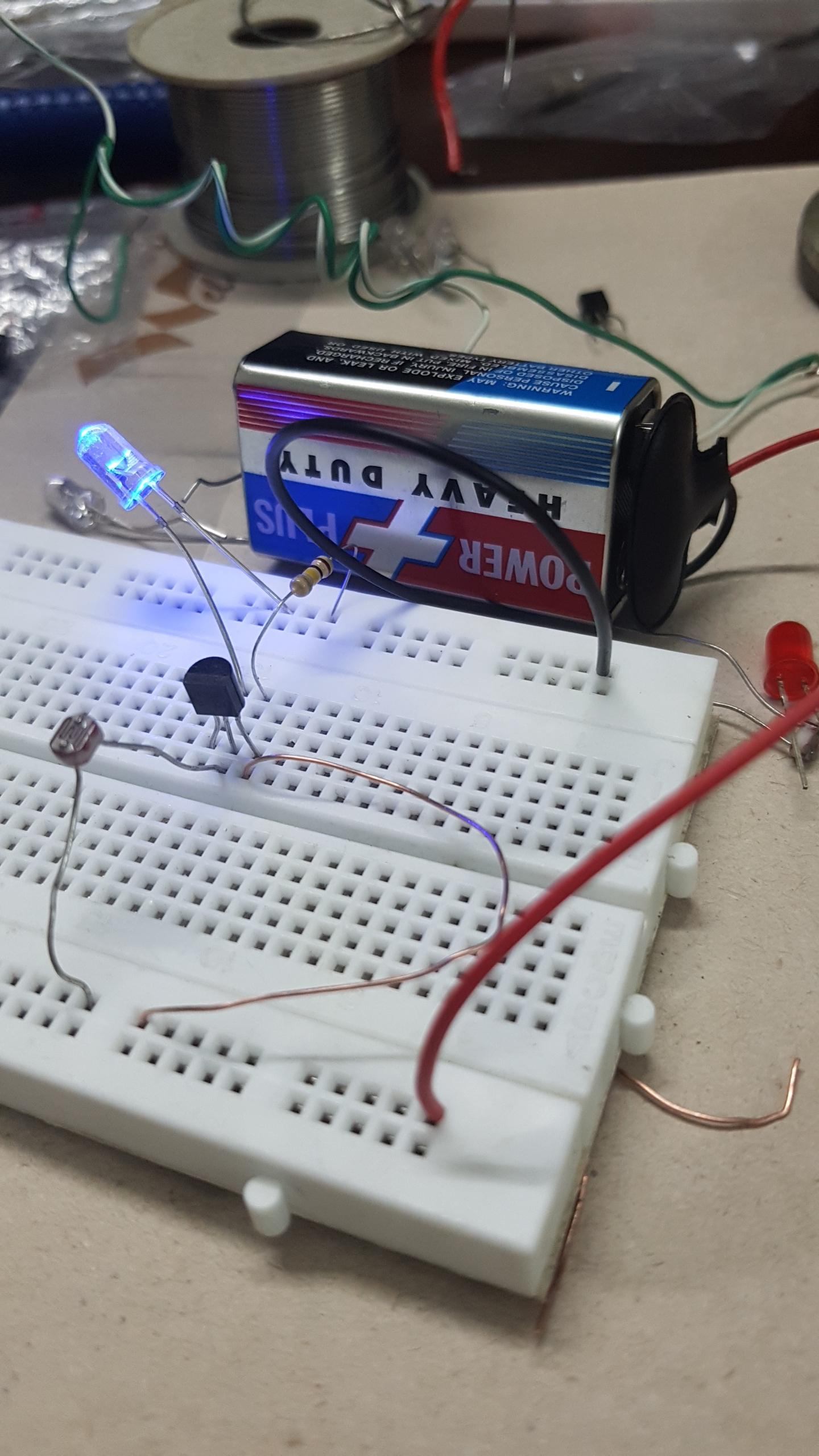
I am stuck on a very simple project since days and i can not figure out what i am doing wrong. The project is about the darkness sensor i.e "the led should light up automatically in darkness and shutt off in light". But in my case its the opposite, led turns off in darkness and turns on in light. I am using and have tried almost all the circuit diagrams from youtube tutorials which are almost the same but with few different resistor values. Also they seem to be using the transistor bc 547 while i am using the bc 548 transistor. Please help me understand what i am doing wrong here?
-
\$\begingroup\$ Draw a schematic. There is a button on the editor toolbar and it is easy to use. Double-click to edit the component values. \$\endgroup\$– TransistorCommented May 24, 2018 at 20:09
-
\$\begingroup\$ You should have a current-limiting resistor of 500 - 1K Ohms in series with the LED. \$\endgroup\$– Peter BennettCommented May 24, 2018 at 20:12
-
\$\begingroup\$ If the wire colors are anything to go by then your battery is connected the wrong way around (and your LED too - which is the only reason it lights up at all). \$\endgroup\$– brhansCommented May 24, 2018 at 20:21
-
\$\begingroup\$ @Petter Bennett. Omg! It finally worked with a 1k ohm resistor. Excited! A million thanks guys. But i would like to make a minor tweak,help me how to increase the sensitivity of the ldr. Because when i connected the led with a 1k ohm in series it was still on under room light and then i thought off shinning the torch light as close as possible on the ldr and it went off. a splendid moment it was. \$\endgroup\$– Syed Suleman ShahCommented May 24, 2018 at 21:08
-
\$\begingroup\$ @SyedSulemanShah Added. \$\endgroup\$– jonkCommented May 26, 2018 at 3:22
2 Answers
Remember that the resistance of the LDR decreases as the light level increases, so in bright light the LDR allows current to flow into the base and causes the transistor to conduct.
You need to swap the LDR and the base resistor. Connect the fixed resistor between the base and 9V; connect the LDR between the base and ground. In bright light the LDR will shunt all of the base current to ground, keeping the LED off. In the dark, the LDR will have a high resistance allowing current to flow through the fixed resistor into the transistor's base, causing it to conduct current.
-
\$\begingroup\$ But that is what is happening already. I want it to stop current in darkness. \$\endgroup\$ Commented May 24, 2018 at 22:19
-
\$\begingroup\$ Anyways its working now with a 1k ohm resistor in serioes to the led just the way i want but sensitivity is too low. Could you help in that? \$\endgroup\$ Commented May 24, 2018 at 22:20
-
\$\begingroup\$ @SyedSulemanShah Are you willing to use more than one BJT? One isn't enough if you want good sensitivity or any hysteresis. Can you also get PNP BJTs? Or do you only have NPN? \$\endgroup\$– jonkCommented May 25, 2018 at 4:29
-
\$\begingroup\$ Yes sure using more than one is fine with me. Yes i have pnp bc 337. \$\endgroup\$ Commented May 25, 2018 at 12:07
Comparator
First, let's look at a very sensitive comparator made from two BJTs. It's a very common arrangement and worth learning about. It's sometimes called a long-tailed pair or a differential amp (diff-amp for short.)
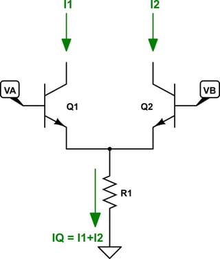
simulate this circuit – Schematic created using CircuitLab
It may look just a little bit complicated at first. But the idea is pretty simple. A BJT's collector current is an exponential function of its base-emitter junction voltage. Since both of these BJTs share the same emitter voltage, you only have to look at the base voltages. If they are exactly the same and if the BJTs are matched up well, then their collector currents will be equal to each other. This means that \$I_1=I_2\$ and each of those will be half the current in \$R_1\$. It's balanced.
But if you make \$V_A\$ just even a little bit higher than \$V_B\$, then \$I_1\$ will be exponentially increased and \$I_2\$ exponentially decreased -- though the sum of the two must still be \$I_Q\$. It turns out that just \$60\:\text{mV}\$ difference between \$V_A\$ and \$V_B\$ is enough to mean that \$I_1=10\cdot I_2\$ or \$I_2=10\cdot I_1\$, depending on which of the two is more positive.
This is a very, very sensitive balance. It weighs \$V_A\$ against \$V_B\$ like a balance scale and tips rapidly towards one side or the other, depending on which side is higher. And it takes almost no difference at all to cause it to tip almost completely over to one or the other side.
So think of this as comparing \$V_A\$ and \$V_B\$. If \$V_A\gt V_B\$ then almost all of the current in \$R_1\$ is from \$I_1\$ and \$I_2\approx 0\:\text{mA}\$. If \$V_A\lt V_B\$ then almost all of the current in \$R_1\$ is from \$I_2\$ and \$I_1\approx 0\:\text{mA}\$.
Adding the LED light
With this nifty balancing scale from above, let me use one side of the scale to turn on the LED.
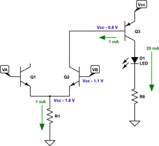
Here, I'm showing the case where the LED is turned ON.
This starts out with noting that the LED current should be in the area of \$20\:\text{mA}\$ and that a red LED drops about \$2\:\text{V}\$. Also, since we want \$Q_3\$ to be saturated, the base current needs to be at least \$1\:\text{mA}\$. (I'm picking a reasonable number, but other choices would also be reasonable -- the main thing is to choose a number that you feel is sure to make \$Q_3\$ saturated, so that it operations like a switch.) From this, I can say that \$R_6=\frac{V_\text{CC}-V_{\text{CE}_\text{SAT}}-V_\text{LED}}{20\:\text{mA}}\$. Given that a \$9\:\text{V}\$ battery can mean that \$7.5\:\text{V}\lt V_\text{CC}\lt 9.3\:\text{V}\$ and that \$V_{\text{CE}_\text{SAT}}\approx 200\:\text{mV}\$ I can work out that a standard resistor value of either \$R_6=270\:\Omega\$ or \$R_6=330\:\Omega\$ would work out fine. Let's select \$R_6=330\:\Omega\$ to operate the LED just a little bit on the light side.
Also, we can estimate that the \$V_\text{BE}\$ of \$Q_3\$ will be about \$800 \:\text{mV}\$. So the base voltage will have to be that much less than \$V_\text{CC}\$, as shown above.
Since we don't need a lot of collector voltage swing for \$Q_2\$, it's enough to reserve about \$300\:\text{mV}\$ added to the base of \$Q_2\$. So I've also shown a hoped-for value for the base of \$Q_2\$. Since the collector current of \$Q_2\$ is a lot lower than the collector current of \$Q_3\$, we can estimate about \$700\:\text{mV}\$ of \$V_\text{BE}\$ for \$Q_2\$. So I've also shown that value at the emitter of \$Q_2\$.
Since I want about \$1\:\text{mA}\$ in \$R_1\$, I can now work out that \$R_1=\frac{V_\text{CC}-1.8\:\text{V}}{1\:\text{mA}}\$. Given the range of \$V_\text{CC}\$ mentioned above, I decide to use \$R_1=6.8\:\text{k}\Omega\$.
Setting the base voltage with a resistor divider
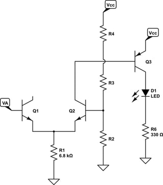
This divider is just a little bit more complicated that you might expect. It uses three resistors instead of two. I'll discuss why, later. For now, let's focus on the details of the divider itself, which still does break down to just two resistances.
We know that the base current for \$Q_2\$ would normally be about a factor of \$\beta=100\$ less than the collector current, or about \$10\:\mu\text{A}\$. But these BJTs will be going into a bit of saturation as they toggle back and forth. So I'm going to double that estimate to a base current of perhaps \$20\:\mu\text{A}\$. A stiff divider would use about 10X that current. So our divider needs a resistance of about \$\frac{V_\text{CC}}{200\:\mu\text{A}}\$. Using the lowest viable battery voltage, we find this means about \$37.5\:\text{k}\Omega\$ ... or less. This also means that there will be \$200\:\mu\text{A}+20\:\mu\text{A}=220\:\mu\text{A}\$ in \$R_3+R_4\$. So \$R_3+R_4\le\frac{1.1\:\text{V}}{220\:\mu\text{A}}=5\:\text{k}\Omega\$. From this, we see that \$R_2\le 32.5\:\text{k}\Omega\$. This is so close to a standard value, that I'm setting \$R_2=33\:\text{k}\Omega\$. This also means that \$R_3+R_4\ge R_2\left(\frac{7.5\:\text{V}}{7.5\:\text{V}-1.1\:\text{V}}-1\right)=5672\:\Omega\$. We'll need this information later.
Adding hysteresis
At this point, it's good to mention the idea of hysteresis for your circuit. This means that when the light is increasing, you use one threshold. But when it is decreasing you use a different threshold. If they were exactly the same, then when the light is close to this single threshold, the LED would flicker a lot. It's better to use slightly different thresholds so that the light has to change by a certain amount before the LED switches state.
For hysteresis, I want to have the means to change the base voltage at \$Q_2\$, depending on the LED ON/OFF state, so that I can move the goal posts (the transition point) for this comparator. Here's the new connections:
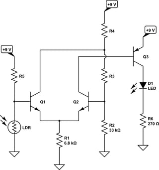
Now, you will see why I divided up the resistor divider chain into three resistors, instead of two. Splitting it up now allows me to alter the divider voltage seen at the base of \$Q_2\$ and you can see that I've taken advantage of this using the \$Q_1\$ collector. The details will become clearer, shortly.
I've also added a simple divider using the LDR and hooked it up to the other side of the comparator, with the LDR placed in a particular position to achieve your goals using this comparator topology.
The hysteresis happens like this: When the LED is ON, as we've been discussing so far, and the LDR resistance is rather low the voltage at the base of \$Q_1\$ is also relatively low. But the base voltage on \$Q_2\$ is rather high at this time. So \$Q_1\$'s collector is basically OFF and it doesn't affect the three resistors used to divide the voltage for the base of \$Q_2\$. The light levels will have to decrease quite a bit in order that the LDR's resistance rises enough so that \$Q_1\$'s base can match the high voltage value at the base of \$Q_2\$. As soon as that happens and the base voltage of \$Q_2\$ does rise high enough, the comparator will tilt in the other direction and \$Q_1\$'s collector will start pulling current through \$R_4\$ and causing an increasing voltage drop across it. This fact will cause the voltage at the base of \$Q_2\$ to drop and that will cause even more collector current in \$Q_1\$ and therefore more voltage drop across \$R_4\$. This is called positive feedback and it rapidly forces a transition to a new state where now there is almost no collector current in \$Q_2\$, turning the LED OFF. Also, \$Q_1\$'s collector current has its final effect on the voltage drop across \$R_4\$, moving the base voltage of \$Q_2\$ down to a new, lower value. Now, the LDR resistance will have to decline (the light hitting it brighter) still more in order to fall below this value and switch the LED back ON, again.
This changing of the goal posts (the voltage level at the base of \$Q_2\$) helps prevent chatter of the LED light when the LDR resistance is near a comparison threshold. If the threshold didn't change, then very slight (imperceptible to you) would cause the LED to change rapidly between ON and OFF. But letting it change somewhat removes this behavior and makes the circuit appear rock solid in its behavior.
Completing the design
This is where I have to make some guesses about your LDR. They aren't all the same. One I have here, a good one, provides about \$5\:\text{k}\Omega\$ in bright room lighting and about \$10\:\text{M}\Omega\$ when dark. Some provide a range more like \$\frac{1}{10}\$th as much. I'm going to pick to resistance values for my hysteresis settings, literally out of the air. Here, I'll use \$R_{\text{LDR}_\text{ON}}40\:\text{k}\Omega\$ (turn ON) and \$R_{\text{LDR}_\text{OFF}}=200\:\text{k}\Omega\$ (turn OFF) as the two values.
Given the newly added LDR divider, I know \$V_\text{CC}\frac{R_{\text{LDR}_\text{OFF}}}{R_{\text{LDR}_\text{OFF}}+R_5}\ge V_\text{CC}-1.1\:\text{V}\$ and also given the battery's voltage range of operation, I find that this solves out so that I should use \$R_5=33\:\text{k}\Omega\$.
Here's a calculated table of values for the \$Q_1\$ base and what I have to guarantee for the base of \$Q_2\$ to make this work. As you can see, the added \$Q_1\$ collector current has to perform some work through \$R_4\$.
$$\begin{align*} V_\text{CC}=9\:\text{V}&\left\{\begin{array}{r|cc} R_\text{LDR}& Q_1 & Q_2\\\hline 40\:\text{k}\Omega & 4.93\:\text{V} & \ge 5.0\:\text{V}\\200\:\text{k}\Omega & 7.73\:\text{V} & \le 7.7\:\text{V}\end{array}\right.\\\\ V_\text{CC}=7.5\:\text{V}&\left\{\begin{array}{r|cc} R_\text{LDR}& Q_1 & Q_2\\\hline 40\:\text{k}\Omega & 4.11\:\text{V} & \ge 4.2\:\text{V} \\200\:\text{k}\Omega & 6.44\:\text{V} & \le 6.4\:\text{V}\end{array}\right. \end{align*}$$
Earlier, I'd mentioned also that \$R_3+R_4\ge 5672\:\Omega\$. Solving the above requirements and this detail suggests that I can use \$R_3=5.6\:\text{k}\Omega\$ and \$R_4=2.2\:\text{k}\Omega\$. Actually, there's a range of values that will work fine. But those are in the general area and should work.
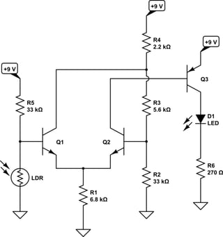
So that's something you might consider trying out.
-
\$\begingroup\$ Thank you jonk but this is pretty confusing and very difficult for me to pick up. I couldnt help myself to understand the whole of it though i picked up the basic information. Thank you. \$\endgroup\$ Commented May 26, 2018 at 19:56
-
\$\begingroup\$ @SyedSulemanShah I added the discussion about designing it for others to read and to also remind myself years later should I need this info myself again. I didn't expect you to follow it that much. But it may help other folks. That said, you might try just building it and see how it works for you. I didn't add a potentiometer to the circuit, though, so you can adjust the threshold. Replace R5 with a 50k Ohm potentiometer would be one way. \$\endgroup\$– jonkCommented May 26, 2018 at 20:09
