1
\$\begingroup\$

My current understanding of the inverting amplifier goes as far as assuming the second golden rule: no current flows through the OpAmp.

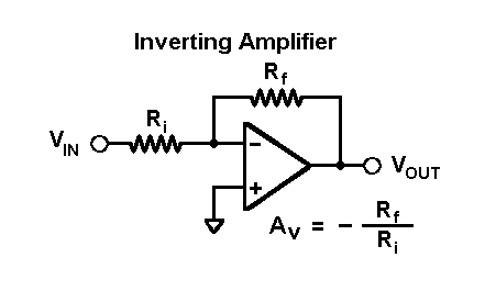
From here on, up to the end result of \$ H(\omega) = -\frac{R_2}{R_1} \$, I'm having a hard time understanding what's going on.

My first confusion arises when applying the superposition rule to obtain the reference voltage \$ U_{-} \$ at the inverted terminal (the non-inverted on being grounded).

https://electronics.stackexchange.com/q/140294/139979

I want to understand this crucial step so I find an expression for the gain voltage \$ G\ U_{-} \$ to which the OpAmp sets its output.

I stumble upon the same problem in calculating the reference voltage at the junction point at \$ V_{out} \$.

I'm not sure of the approach of converting this circuit into a Thevenin equivalent circuit, by treating the OpAmp as a current source, either.

For the problem at hand, I don't assume the first golden rule where \$ G(U_{+} - U_{-}) = 0 \$. This is what I actually want to derive. :)

\$\endgroup\$
1

3 Answers 3

6
\$\begingroup\$

I normally would just rush forward with the obvious voltage divider equation. But I'm going to assume, because you reference it, that you want each voltage source activated one at a time while all other voltage sources are "shorted." It's more busy work. Oh, well.

You only have two voltage sources, \$V_\text{IN}\$ and \$V_\text{OUT}\$. So this isn't too much work. With \$V_\text{IN}\$ active and \$V_\text{OUT}=0\:\text{V}\$. There is a current \$\frac{V_\text{IN}}{R_i+R_f}\$. With \$V_\text{OUT}\$ active and \$V_\text{IN}=0\:\text{V}\$. There is a current in the opposite direction, \$\frac{V_\text{OUT}}{R_i+R_f}\$. The sum of these two superimposed currents is then \$\frac{V_\text{IN}}{R_i+R_f}-\frac{V_\text{OUT}}{R_i+R_f}\$. To find the voltage at the inverting terminal, we start with \$V_\text{OUT}\$ and add the voltage drop across \$R_f\$, so we find that:

$$\begin{align*} V_-&=V_\text{OUT}+R_f\cdot\left(\frac{V_\text{IN}}{R_i+R_f}-\frac{V_\text{OUT}}{R_i+R_f}\right)\\\\ &=V_\text{OUT}+R_f\cdot\frac{V_\text{IN}-V_\text{OUT}}{R_i+R_f}\\\\ &=\frac{V_\text{OUT}\:R_i+V_\text{OUT}\:R_f+V_\text{IN}\:R_f-V_\text{OUT}\:R_f}{R_i+R_f}\\\\ &=\frac{V_\text{OUT}\:R_i+V_\text{IN}\:R_f}{R_i+R_f}\label{eq1}\tag{1} \end{align*}$$

But you know, given that the non-inverting terminal is grounded, that \$V_\text{OUT}=-G\cdot V_-\$. So:

$$\begin{align*} V_-&=\frac{V_\text{OUT}\:R_i+V_\text{IN}\:R_f}{R_i+R_f}\\\\ &=\frac{-G\: V_-\:R_i+V_\text{IN}\:R_f}{R_i+R_f}\\\\&\therefore\\\\ V_-&=V_\text{IN}\frac{R_f}{R_f+R_i\left(G+1\right)}=V_\text{IN}\frac{1}{1+\frac{R_i}{R_f}\left(G+1\right)} \end{align*}$$

Then,

$$\begin{align*} V_\text{OUT}&=-G\cdot V_-=-G\cdot V_\text{IN}\frac{R_f}{R_f+R_i\left(G+1\right)}\\\\&\therefore\\\\ \frac{V_\text{OUT}}{V_\text{IN}}&=-G \frac{R_f}{R_f+R_i\left(G+1\right)}\\\\ &=\frac{-R_f}{\frac{R_f}{G}+R_i\frac{G+1}{G}}=\frac{-R_f}{\frac{R_f+R_i}{G}+R_i} \end{align*}$$

As \$G\to\infty\$ then \$\frac{V_\text{OUT}}{V_\text{IN}}=\frac{-R_f}{R_i}\$.

Not sure if that's what you wanted, though.


Nodal, done my way

I gather you worry about keeping the signs right. I also worry about that, too. I dislike, with some vigor, the way that nodal analysis is usually taught, where you have to consistently keep track (and continually re-inforce it mentally) of what is being subtracted from what. So here is my nodal approach that makes it a lot easier (for me) and I never worry about signs.

I set up the nodal equations such that outflowing currents are on the left and inflowing currents are on the right. Note that there are no minus signs anywhere.

Imagining myself as standing in the middle of the \$V_-\$ node:

$$\begin{align*} \frac{V_-}{R_i}+\frac{V_-}{R_f}&=\frac{V_\text{IN}}{R_i}+\frac{V_\text{OUT}}{R_f}\\\\ V_-\left(\frac{1}{R_i}+\frac{1}{R_f}\right)&=\frac{V_\text{IN}}{R_i}+\frac{V_\text{OUT}}{R_f}\\\\ V_-\left(\frac{1}{R_i}+\frac{1}{R_f}\right)\frac{R_i\:R_f}{1}&=\left(\frac{V_\text{IN}}{R_i}+\frac{V_\text{OUT}}{R_f}\right)\frac{R_i\:R_f}{1}\\\\ V_-\cdot\left(R_f+R_i\right)&=\left(V_\text{IN}\:R_f+V_\text{OUT}\:R_i\right)\\\\ V_-&=\frac{V_\text{OUT}\:R_i+V_\text{IN}\:R_f}{R_i+R_f}\label{eq2}\tag{2} \end{align*}$$

You can see that eq. \$\ref{eq1}\$ matches eq. \$\ref{eq2}\$.

It's a lot easier, I think, to handle the signs consistently and flawlessly, time after time, this way. Mentally stand in the middle of each node and just put all the outflowing currents on the left; all the inflowing currents on the right; and the rest just follows trivially. I learned this technique by observing source code for a Spice program and seeing how it handled the equation setup. Made a lot of sense to me and I've never gone back to the book-learned way, which I now consider to be designed for failure.

(Now imagine that you had to include an input impedance for the opamp. Easy. Let's call that input impedance, \$R_\text{in}\$. On the left side, you'd simply add \$\frac{V_-}{R_\text{in}}\$. On the right side, you'd add \$\frac{V_+}{R_\text{in}}\$. That's it. The process is trivial to follow. You almost cannot mess up.)
\$\endgroup\$
4
  • \$\begingroup\$ How do you keep track of the signs of the voltage drops? For instance, it is now vaguely clear to me, that to calculate the voltage at the inverted terminal \$V_{-}\$ we start out with \$V_{out}\$ and then add the voltage drop across \$R_f\$. I'm not completely sure why we are adding the voltage drops across \$R_f\$ and not subtracting it. \$\endgroup\$ Commented May 29, 2018 at 8:10
  • \$\begingroup\$ @MusséRedi For me, it's just a matter of holding a consistent perspective while writing. I set up the currents (one being subtracted from the other) on the basis of starting at \$V_\text{OUT}\$ and adding the voltage drop. So I started with my intent and followed through. Your confusion is one reason why I so much dislike the way nodal is taught and prefer a different approach. I'll add a nodal analysis, my style and not the style usually taught, at the bottom that should help. \$\endgroup\$
    – jonk
    Commented May 29, 2018 at 13:38
  • \$\begingroup\$ If \$V_{out}\$ is active and the current is in the other direction, shouldn't we have a sign change with respect to the current when \$V_{in}\$ is active? I.e. a current $$\frac{(\text{-})V_{out}}{R_i +R_f} $$ when \$V_{out}\$ is active? \$\endgroup\$ Commented Jun 3, 2018 at 19:53
  • \$\begingroup\$ Or never mind, I see that you've added a minus sign when you took the sum of the currents. :) \$\endgroup\$ Commented Jun 3, 2018 at 19:57
4
\$\begingroup\$

Applying the superposition principle, is the most simple method for finding the closed-loop gain of the inverter circuit. As long as the opamp is operated within its linear region we can set the resulting voltage Vn between ground and the inverting terminal Vn=0 (in reality it is as small as some µVolts).

Superposition:

(1) Vout=0: Vn1=Vi*Rf/(Ri+Rf)

(2) Vi=0: Vn2=Vout*Ri/(Rf+Ri)

(3) Setting Vn=Vn1+Vn2=0 we arrive at Vout/Vi=-Rf/Ri

EDIT: Finite Aol.

For finite Aol we have Vn=Vn1+Vn2=-Vout/Aol

This expression leads to Vout/Vin=-Rf/[Ri+(Ri+Rf)/Aol]

For Aol infinite this expression reduces again to Vout/Vi=-Rf/Ri

\$\endgroup\$
8
  • \$\begingroup\$ Why can we set the voltage \$V_n\$ between ground and the inverting terminal to 0? \$\endgroup\$ Commented May 29, 2018 at 7:53
  • \$\begingroup\$ Which voltages refer to \$V_{n1}\$ and \$V_{n2}\$ respectively? \$\endgroup\$ Commented May 29, 2018 at 7:54
  • \$\begingroup\$ For superposition of two voltage sources (here we have two soureces: Vi and Vout) we calculate the circuit parameters in two separate steps: Vn1 is the voltage at the inverting n-terminal as caused by Vi only and Vn2 is the voltage at this input terminal caused by Vout only. Then we add both parts to get the resulting voltage vn. For ideal opams, we may set Vn=0 and for real opams we set Vn=-(Vout/Aol) with Aol=open-loop gain. \$\endgroup\$
    – LvW
    Commented May 29, 2018 at 8:01
  • \$\begingroup\$ Okay, so now my question is: what is the n-terminal? \$\endgroup\$ Commented May 29, 2018 at 8:02
  • \$\begingroup\$ Why Vn=0 ? Answer: As long as the whole circuit operates in its linear amplification region (not saturated) the input voltage at the inverting terminal is always Vn=-(Vout/Aol). Since the open-loop gain of the opamp is very large (1E4...1E5), the voltage Vn is very small (usually in the microvolt range). This small voltage can be neglected in most cases aginst the input voltage Vi and the ouput voltage Vout (usually in the upper millivolt or in the volt range). Hence, for calculation we are allowed to set Vn=0 - and the resulting error is very small. Otherwise, we set Vn=-(Vout/Aol). \$\endgroup\$
    – LvW
    Commented May 29, 2018 at 8:10
1
\$\begingroup\$

If I understand your question correctly, the main goal you have is to show how the op-amp has a transfer function of \$A(s) = -R_2/R_1\$. If we're performing ideal op-amp analysis- which you seem to be starting to do- then there are 2 "golden" rules (Let's use them to get the transfer function and then we'll come back to why they are the way they are):

  1. No current flows through the input terminals of the opamp.
  2. The voltage at the input terminal nodes are the same (only in a closed loop).

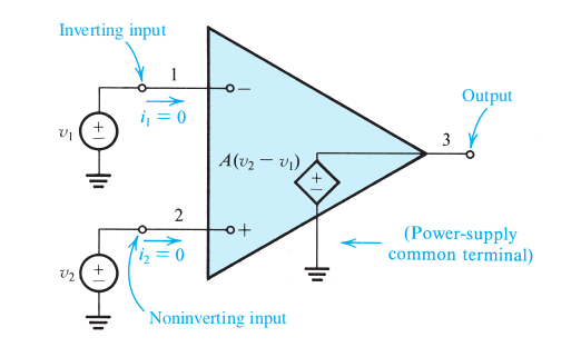
For reference here is a figure of an ideal op-amp, from Sedra and Smith. enter image description here

With these two rules we can start analyzing the circuit. The first thing I like to do is to try and list all the quantities I know. In this case, since the non-inverting terminal is grounded, by rule 2 we have that the voltage at the inverting terminal node is 0V. From here we can perform a nodal analysis to find \$A(s) = V_{out}(s)/V_{in}(s)\$. Performing a KCL at the inverting terminal node (and noting from rule 1 that no current flows to the inverting input terminal): $$\frac{V_{in}(s)-0}{R_1} + \frac{V_{out}(s)-0}{R_2} = 0$$ From here a little algebra gives the result.

Now going back to why the goldren rules are why they are: they are actually a consequence of several "ideal" assumptions that we make about the op-amp. Most textbooks will list the same assumptions that wikipedia does, but the ones that relate to rule 2 are mainly infinite open loop gain.

Consider the op-amp from the figure above. The op-amp is basically a difference amplifier, it takes the difference in voltage between the two terminals and multiplies it by its gain \$A\$. In a closed loop, if the op-amp is working- i.e. it is providing a finite output, then by its TF the relation \$A(v_2-v_1) = v_o\$ exists. Then, $$v_2-v_1 = \frac{v_0}{A}$$If \$A\$ is infinite, from our ideal assumption, then that means \$v_2-v_1=0\$ and thus rule 2 is established.

\$\endgroup\$
8
  • 1
    \$\begingroup\$ I have not gained any further understanding from reading this answer. My end-goal is to, indeed, understand why the first golden rule holds after assuming \$ A \gg \frac{R_f}{R_i} \gg 1 \$. My starting point is a non-ideal OpAmp, from which I want to arrive at the second golden rule. I do not want to assume the first golden rule from the start. The closing argument that you're making, taking \$A\$, doesn't give any insight from the circuit analysis perspective. I want to use a similar argument, using $ A \gg \frac{R_f}{R_i} \gg 1 \$, in the TF expression. \$\endgroup\$ Commented May 28, 2018 at 22:32
  • \$\begingroup\$ Furthermore, could you elaborate on performing a KCL? \$\endgroup\$ Commented May 28, 2018 at 22:33
  • \$\begingroup\$ @MusséRedi Are you just trying to show that the voltage at the inverting input is small, while willing to use a starting assumption that the opamp's inputs neither sink nor source current? I'm honestly not sure what you accept as axioms and what your goal might be. \$\endgroup\$
    – jonk
    Commented May 28, 2018 at 22:45
  • \$\begingroup\$ @MusséRedi Or do you also require the use of setting all voltage sources to zero, except one; each in turn? You reference "superposition" but I've seen so many different ways of "seeing superposition" that I'm not sure what's required there. \$\endgroup\$
    – jonk
    Commented May 28, 2018 at 22:55
  • \$\begingroup\$ @jonk My starting assumption is that no current goes through the OpAmp; in has an infinite input impedance. From here on, I want to derive the transfer function for the non-ideal inverting amplifier. Upon assuming a large gain, it will then become apparent that the OpAmp's input difference does indeed become negligible. This is the approach I'm aiming at. \$\endgroup\$ Commented May 28, 2018 at 22:56

Your Answer

By clicking “Post Your Answer”, you agree to our terms of service and acknowledge you have read our privacy policy.

Not the answer you're looking for? Browse other questions tagged or ask your own question.