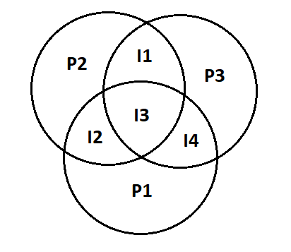
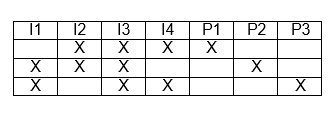
Here's your diagram, given your table. This diagram makes things really easy to understand, I think:

This is just another way of writing your table, except more visual and quicker to navigate without holding things in your head while you read a row.
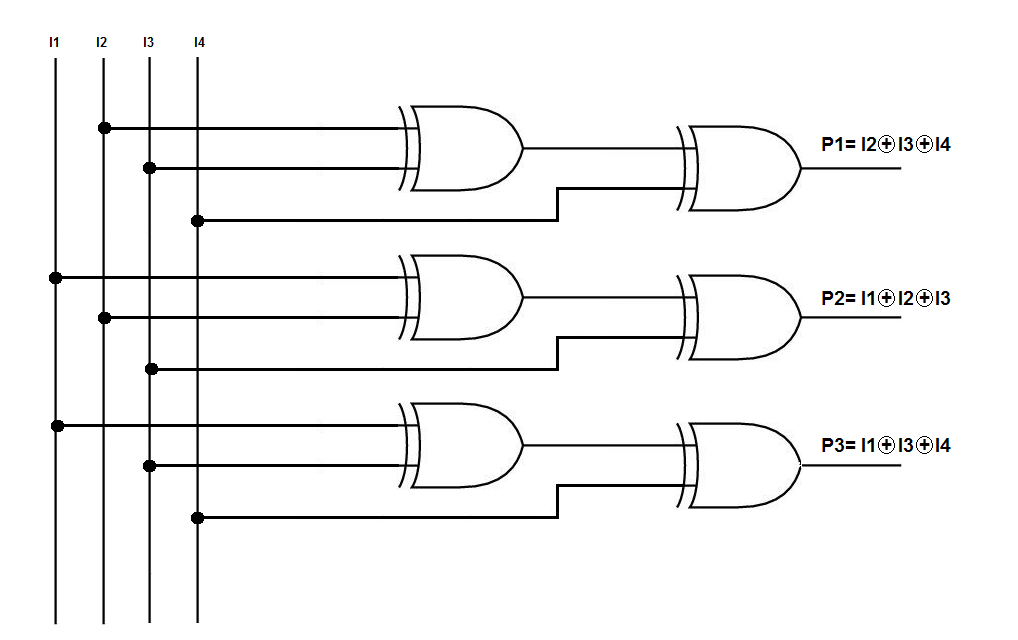
The original generators, \$P_1\$, \$P_2\$, and \$P_3\$, will have produced their values as a result of generating parity for the values within their circle. Doesn't really matter if this is odd or even parity generation, so long as the receiver of the message shares the method. This generates 7 total bits out of 4 data bits.
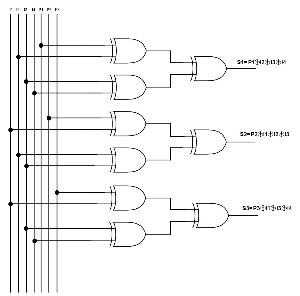
Upon receipt, a receiver performs the same function using generators \$P_1\$, \$P_2\$, and \$P_3\$ to replicate the work, applying them to the received 4 data bits. This produces another set of three generated parity values, which can now be compared with the parity bits included in the 7-bit message. (Using an XOR or XNOR.)
There are eight possible combinations of these three comparison bits. But if the generated parities match up with the transmitted parities, then there is no single-bit error (this doesn't entirely exclude multi-bit errors.) So that accounts for one of the combinations, leaving seven to consider.
It's possible that one of the parity bits is itself the error and that the data bits are just fine. But if that's so, then only one of the comparisons will produce an error. If only one, then it is a parity bit error. There are exactly three possible cases where only one comparison generates an error. So this accounts for three more combinations, leaving only four remaining to consider.
(You can choose to correct the parity bit, but I think that's pointless. If you want to correct the parity bits you can do that merely by accepting your own generated parities.)
There are three combination where two of the comparisons generate an error. These will account for those data bits which affect two parity bits. And there is only one combination which affects all three parity bits. From the diagram above, it should be very easy to see which are which. Those are the data bits that might have singly been corrupted and they should be appropriately inverted to get back the original value.


