4
\$\begingroup\$

I need to drive several indicator LEDs at <2mA. Each LED has a nominal Vf between 3.2V and 3.3V (Vf max up to 4V).

In the past I've had the luxury of (a) current-limiting resistors or (b) constant-current power supplies.

But what do I do when my entire circuit has to run off a single 3.3V SMPS, and the microprocessor outputs are limited to 25mA? Here solution A isn't applicable, and the budget doesn't allow solution B (unless maybe all the LEDs can share a single current-limited supply--they don't all have to be on at the same time--and yet I still get to control the LEDs from a microprocessor directly, without external transistors.)

Background:

  1. I have a microprocessor with a few PWM outputs, but not enough for every LEDs. (yes, multiplexing is possible)
  2. This is an ultra-low-power, portable application.
  3. BOM cost has to be low, low, low.
\$\endgroup\$
5
  • 1
    \$\begingroup\$ Consider using different colour LEDs, like RED? Then (a) becomes possible. \$\endgroup\$
    – glen_geek
    Commented Jul 18, 2018 at 19:39
  • 1
    \$\begingroup\$ True that. These LEDs were chosen specifically for their awesome brightness at low currents. They aren't exactly "indicator LEDs," but they are also not lighting my house. \$\endgroup\$
    – mcpublic
    Commented Jul 18, 2018 at 20:00
  • 1
    \$\begingroup\$ Yes you can with Vf dropping to 2.9@2mA typ so from logic port Vol/Iol=ESR add R’s to drop about 4xx mV /2 mA =200 Ohms +\-50% depending on chip specs , driver ESR and Vss tolerance you can reduce deviation of current. I have about 10k pcs of >16 Cd white 5mm LEDs that work well at 1mA \$\endgroup\$
    – D.A.S.
    Commented Jul 18, 2018 at 20:04
  • 1
    \$\begingroup\$ Thanks Tony. You bring up a great point that I'd totally forgotten about: The spec'd Vf is at 20mA. Under-driving the LED at 2mA gives me plenty of (Vdd-Vf) voltage drop to use a current-limiting resistor. Still, too bad I have to dissipate any power across the resistor, but power supply chips cost money, and ya gotta compromise somewhere. (BTW... If you'd submitted this as an answer, I'd have chosen it.) \$\endgroup\$
    – mcpublic
    Commented Jul 18, 2018 at 20:14
  • 1
    \$\begingroup\$ There are more of this kind of questions answered, electronics.stackexchange.com/q/378099/117785 and electronics.stackexchange.com/q/364758/117785 \$\endgroup\$ Commented Jul 18, 2018 at 21:17

2 Answers 2

1
\$\begingroup\$

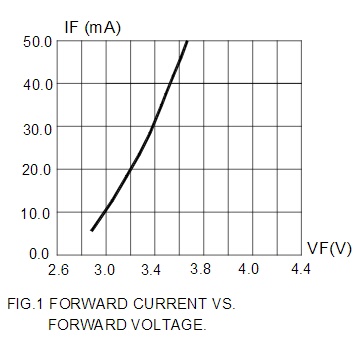
The nominal Vf for an led in a datasheet is given for a nominal If. If your If is less than the If at the nominal Vf, then it won't conduct at that nominal forward voltage. Always look at the Vf vs If graph for your chosen led, or test it with a constant current test circuit.

Also remember, that all those values are average, and your specific led may be above or below the average value. One led may be 3mA and another at 1mA for the same brightness, and at this low values, you may want to test and adjust resistors for each led.

\$\endgroup\$
0
\$\begingroup\$

With lower current the Vf will be lower too.

This Cree 48,000 mcd typical @ 20 mA C503D-WAN also has similar characteristics as yours: 3.2 Vf typical and 4V max.

At 2 mA Vf = 2.9V.

enter image description here


But you do not need 2 mA if you use an LED with high efficacy.

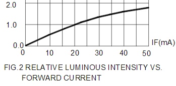
The Cree LED I referenced has a linear IV slope from 0 to 20 mA.

At 2 mA you'd have 4,800 mcd
At 200 µA you'd still have 480 mcd.

At 200 µA your Vf will likely be less than 2.5V and the LED will be very visible.

enter image description here


(a) current-limiting resistors
solution A isn't applicable

This is likely not true. You could use a 1K resistor.
A µ-controller's Vol will be about 0.5V giving you 2.8V to 3.3 VDD which gives you enough overhead to satisfy the LED's Vf


How to gain 0.3 volts V @ 10 mAf

Sometimes the small stuff counts.
Such a case is where the supply is very close to the Vf
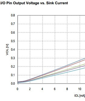
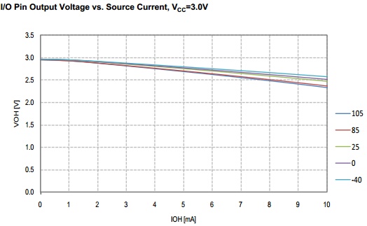
The following are for an Atmel attiny441 with a supply of 3.0V.
This is applicable only when you sink the LED current.
In this case the I/O pins max sink is 20 mA and max source is 10 mA.

At 10 mA the source voltage difference is greater than 0.5V.
At 10 mA the sink voltage difference is less than 0.3V.

At 25°C and 10 mA the sink VOL is 0.2V
At 25°C and 10 mA the source VOH is 2.5V

enter image description here

enter image description here

If you could use a SMT LED then you should use a Samsung LM301B.

\$\endgroup\$
2
  • 2
    \$\begingroup\$ I disagree with your statement that the IO sink current is "generally" greater than the source current. The Cortex-M processors I've been using have symmetric output drive. Asymmetric drive is a holdover from the TTL days. \$\endgroup\$ Commented Jul 19, 2018 at 1:54
  • \$\begingroup\$ @ElliotAlderson I removed the debatable points. \$\endgroup\$ Commented Jul 22, 2018 at 22:51

Not the answer you're looking for? Browse other questions tagged or ask your own question.