0
\$\begingroup\$

I am attempting to create a circuit using a TUSB2036 usb hub IC that automatically starts when it is powered on.

The datasheet states for the inverted RESET pin

RESET is an active low TTL input with hysteresis and must be asserted at power up. When RESET is asserted, all logic is initialized. Generally, a reset with a pulse width between 100μs and 1 ms is recommended after 3.3-V Vcc reaches its 90%.

My understanding is that this means I have to supply a delayed (to allow the power to fully initialise), active low (because the RESET pin is active low), ~1ms pulse that is triggered when the power is connected. Is this correct?

If so, how would I go about doing this? I have tried using a 555 timer but I can't get it to work. I tried looking up monostable 555 timer circuits but they all the ones I found are effectively pulse extenders which is not what I need. I also found this question that also used a 555 timer but I was unable to use the circuit in the answers to generate a pulse that is short enough.

Is using a 555 timer the way to do this or is there a different IC that do this simpler. I don't really have any particular constraints apart from the usual cheaper and simpler.

Thanks.

\$\endgroup\$
1
  • 1
    \$\begingroup\$ I am attempting to create a circuit using a TUSB2036 usb hub IC that automatically starts when it is powered on. ............. why don't you just simply refer to the application schematics on the TI website? \$\endgroup\$
    – jsotola
    Commented Jul 25, 2018 at 2:25

3 Answers 3

3
\$\begingroup\$

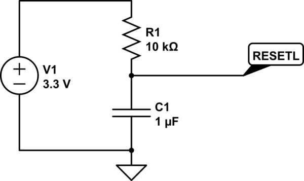
Just use an RC from +3.3V to GND with a time constant of ~10ms or so as shown below. The voltage on the cap should stay below threshold long enough to reset the part. This is a standard low cost way of implementing an active low power up reset, especially when the input already has hysteresis.

schematic

simulate this circuit – Schematic created using CircuitLab

\$\endgroup\$
1
  • 1
    \$\begingroup\$ Change that resistor to 15K and this matches TI's application schematic exactly. \$\endgroup\$ Commented Jul 25, 2018 at 4:45
1
\$\begingroup\$

You need a circuit called "voltage supervisor and reset IC", there are hundreds of variants like TLV803, APX811, MAX809, etc. You don't need to generate minimally short pulse, anything longer than required minimum would do the job.

\$\endgroup\$
1
\$\begingroup\$

While you can certainly use a 555 for this, I would highly recommend using a dedicated reset IC for this instead.

There are ICs whose sole purpose is to monitor a voltage and produce a reset signal. They are called voltage supervisors.

As for the nature of the pulse it would actually be better to power up the part with the reset input asserted (meaning held low) and then release it high 100us to 1ms after VCC has reached 90% of its nominal value, rather than letting reset power up with VCC and then pulsing it later. The purpose of keeping reset low as VCC ramps is to prevent the outputs from doing anything weird as VCC rises, so holding that input low ensures that part is held in reset until such a time as the part is within the voltage range where its operation is guaranteed.

Here's an example digikey search for voltage supervisors: https://www.digikey.com/products/en/integrated-circuits-ics/pmic-supervisors/691?k=&pkeyword=&pv183=2553&FV=ffe002b3&quantity=0&ColumnSort=0&page=1&pageSize=25

\$\endgroup\$
4
  • \$\begingroup\$ Hi. Thank you for your answer. What benefits would a voltage supervisor have over using the RC that crj11 suggested? \$\endgroup\$
    – JamesStewy
    Commented Jul 25, 2018 at 4:10
  • 1
    \$\begingroup\$ The voltage supervisor will be more exact with its timing and generally not vary with temperature. The RC circuit depends both on the temperature of the capacitor and the threshold voltage of the ~RESET pin (which can vary considerably part to part and also by temperature). Also, some types of CMOS logic don't like slow edges (they will dissipate excessive power during the transition) and so an RC circuit wouldn't work very well in that case since it would be stressing the IC. \$\endgroup\$ Commented Jul 25, 2018 at 4:42
  • 1
    \$\begingroup\$ Looking at the application schematic, they actually do use an RC circuit, so the TUSB2036 should work fine with that solution. \$\endgroup\$ Commented Jul 25, 2018 at 4:45
  • \$\begingroup\$ RC would fail under "brown-out" condition (partial loss of power, where all circuit parameters might become undefined at random), while the supervisor circuit will generate a perfect reset. The RC will only work if the hub is bus-powered, and likely fail if the hub is self-powered and brown-out happens.. \$\endgroup\$ Commented Jul 25, 2018 at 5:11

Your Answer

By clicking “Post Your Answer”, you agree to our terms of service and acknowledge you have read our privacy policy.

Not the answer you're looking for? Browse other questions tagged or ask your own question.