14
\$\begingroup\$

I'd like to test USB full speed with a goal of testing high speed (480 Mbit/s), I have a tek scope that does 300 MHz (which I could upgrade to 500 MHz) and I'm looking at a 500 MHz differential probe. As I understand it I also need a breakout board (which I'm not quite sure is the best thing to get), but I'm looking at this board from tek and one listed here.

What are the minimum requirements for a test like this?

Is this equipment list sufficient to preform an eye diagram test for full speed USB?

Is this equipment list sufficient to preform an eye diagram test for full speed USB if I have a 500 MHz scope?

\$\endgroup\$
1
  • \$\begingroup\$ The eye pattern tests use SMA 50 ohm terminations with good coax but the diff probes can measure in-circuit. \$\endgroup\$
    – D.A.S.
    Commented Aug 28, 2018 at 18:57

4 Answers 4

10
\$\begingroup\$

What are the minimum requirements for a test like this?

Minimum requirements for test equipment to use for USB 2.0 signal quality evaluation is listed at USB.org in the following place. There are links that describe electrical test procedures and tool requirement for Rohde & Schwarz, Tektronix, Agilent, LeCroy, and Yokogawa oscilloscopes.

Typically the eye evaluation software tools are offered on scopes with no less than 2GHz bandwidth. For Tektronix, the eligible scope series are TDS7254/B, TDS7704/B, CSA7404/B, TDS6604/B, TDS6804/B, TDS6404, DPO7254, DPO7354, and DPO/DSA70000. The smallest eligible oscilloscope for USB 2.0 testing is MSO/DPO5204.

For FS evaluation you don't need differential probes, the scope does it mathematically using single-ended probes.

However, the software package can't be installed on smaller bandwidth scopes, so, even if 500 MHz bandwidth is OK for FS eyes, it is unlikely that you can use this scope.

\$\endgroup\$
6
  • \$\begingroup\$ Yeah, I think I'm out of luck on the HS testing, a new scope would be a significant capital expenditure. I'll stick with single ended testing on FS. I don't have that many HS devices anyway. \$\endgroup\$
    – Voltage Spike
    Commented Aug 28, 2018 at 21:46
  • 1
    \$\begingroup\$ @laptop2d, DPO5204 is just $23K, and you will need a set of test fixtures, the cheapest one is from Allion for $1700, shop.allion.com/Product_List.asp?iGroupNum=4 The optional USB package might cost as well, but it may come with the test fixture. For HS you will need P6248 diff probe, another $6K. Yes, real USB development is pricey. \$\endgroup\$ Commented Aug 29, 2018 at 0:08
  • 1
    \$\begingroup\$ You didn't mention that for the EYE PATTERN test the 2GHz probes must active FET buffered DIFF probes, ultra-balanced and ultra-low capacitance and ultra sensitive to ESD ( > 25V as I recall not 1kV) not just any 2 probes. \$\endgroup\$
    – D.A.S.
    Commented Aug 29, 2018 at 5:01
  • 1
    \$\begingroup\$ Although Yokogawa has some nice 5GHz passive 500 Ohm 10:1 probes. 0.25pF 70ps Model 701974 PBL5000 5-GHz \$\endgroup\$
    – D.A.S.
    Commented Aug 29, 2018 at 5:20
  • \$\begingroup\$ @TonyEErocketscientist, I also forgot to mention that HS USB testing needs a pricey pattern generator (variable amplitude HS pattern at nanosecond rate), to test for very important parameter as receiver sensitivity (squelch/unsquelch), and that old probes would likely need expensive adapters (~$500 each) to accommodate the modern "Tek-probe" interfaces, unless the native TAP1500 probes (~$3K each) are purchased. \$\endgroup\$ Commented Aug 29, 2018 at 16:21
9
\$\begingroup\$

If your signal has a fundamental at 500MHz, and you're trying to measure its characteristics, then you're not going to do well with a 500MHz scope because the scope won't capture any of the harmonics. You will need a higher bandwidth scope and probe if you want to make an accurate measurement of what's happening.

\$\endgroup\$
2
  • 1
    \$\begingroup\$ How about for full speed? \$\endgroup\$
    – Voltage Spike
    Commented Aug 28, 2018 at 19:51
  • 1
    \$\begingroup\$ USB full speed is 12Mbit/s which is much less than 1/10-1/5 of your scope's bandwidth, so you should be able to do the measurement. \$\endgroup\$
    – C_Elegans
    Commented Aug 29, 2018 at 0:47
7
\$\begingroup\$

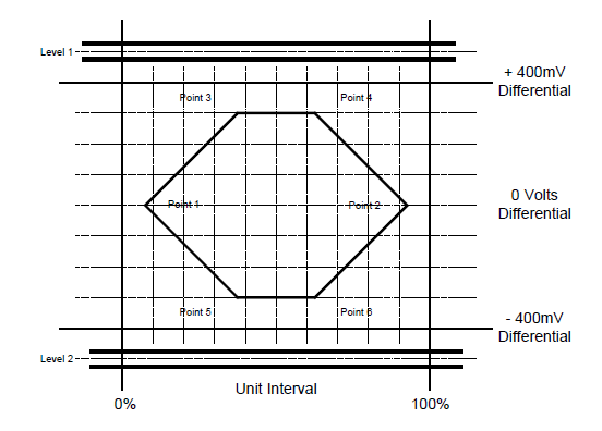
To test a USB high speed transmitter, you have to test the TP3 mask:

enter image description here

The horizontal position of point 3 is at 37.5% UI, and point 6 is at 62.5% UI, so you are trying to measure a rise-time of about 75% of 2.08 ns, or about 1.5 ns.

A 500 MHz scope will measure a minimum risetime of about \$0.75/500\ {\rm MHz}\$, or 1.5 ns.

You can estimate the risetime you measure will be about

$$\tau_{meas}\approx\sqrt{\tau_{scope}^2+\tau_{sig}^2},$$

so a 500 MHz scope is not going to cut it. I'd look for at least 1 GHz, and 2 GHz will help if your product doesn't have much margin.

\$\endgroup\$
4
  • 2
    \$\begingroup\$ This mask is for HS eye, while OP is asking about FS evaluation. \$\endgroup\$ Commented Aug 28, 2018 at 21:38
  • 5
    \$\begingroup\$ @AliChen, OP says they want to test "480mbit". That's high speed, not full speed. In any case they can use the same methodology to evaluate whether their instrument is adequate for full speed. \$\endgroup\$
    – The Photon
    Commented Aug 28, 2018 at 21:46
  • \$\begingroup\$ @ThePhoton I disagree with 0.75/f I know that the rise time is closer to 0.35/f as my LeCroy shows an arc with ~1ns rise time (10~90%) for ~300MHz BW consistent with theory. I can show photo and proof if you like. \$\endgroup\$
    – D.A.S.
    Commented Aug 29, 2018 at 18:25
  • \$\begingroup\$ Maybe you are using 0 to 100% \$\endgroup\$
    – D.A.S.
    Commented Aug 29, 2018 at 18:35
4
\$\begingroup\$

I ended up using a single ended measurement and using matlab to poll the textronix scope and using the instrument control toolbox:
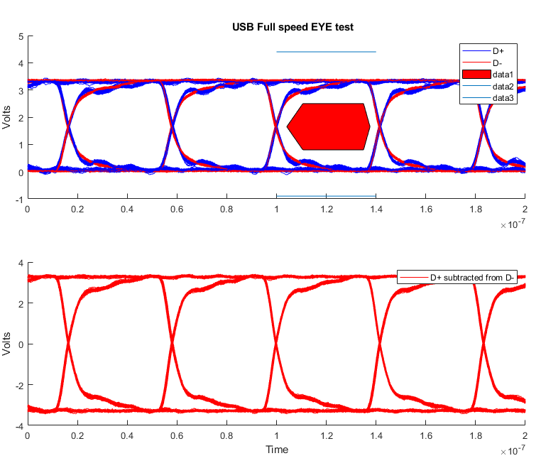
enter image description here

myScope = oscilloscope
drivers(myScope)
availableResources = getResources(myScope)
availableResources{5}
myScope.Resource = 'TCPIP::xxx.xxx.xxx.xxx::INSTR'
connect(myScope)
get(myScope)
waveformArray = getWaveform(myScope, 'acquisition', true);
figure;plot(waveformArray)
enableChannel(myScope,'CH3');
enableChannel(myScope,'CH4');
Time = linspace(0,myScope.AcquisitionTime,myScope.WaveformLength);
aqs = 1000;
for i = 1:aqs
[w3, w4] = readWaveform(myScope, 'acquisition', true);
pause(0.05);
w3mat{i} = w3;
w4mat{i} = w4;
end
figure;subplot(2,1,1),hold on,legend('D+','D-'),subplot(2,1,2),hold on
for i = 1:aqs
w3 = w3mat{i};
w4 = w4mat{i};
subplot(2,1,1)
plot(Time,w3,'b'),plot(Time,w4,'r')
subplot(2,1,2)
plot(Time,w3-w4,'r')
end
subplot(2,1,1),legend('D+','D-'),ylabel('Volts');
subplot(2,1,2),legend('D+ subtracted from D-'),xlabel('Time'),ylabel('Volts');
subplot(2,1,1)
x = [8.2  21.15 69.93 75.13 69.93 21.15 8.2 ]*1e-9/2;%These come from the USB IF website specs
y = [1.65 2.5   2.5   1.65  0.8   0.8   1.65];
fill(x+1e-7,y,'r')
title('USB Full speed EYE test')
line([1e-7 1.4e-7  ],[-0.9  -0.9])
line([1e-7 1.4e-7  ],[4.4  4.4])
\$\endgroup\$
1
  • 3
    \$\begingroup\$ You should accept this as the answer then \$\endgroup\$
    – endolith
    Commented Apr 19, 2023 at 19:42

Your Answer

By clicking “Post Your Answer”, you agree to our terms of service and acknowledge you have read our privacy policy.

Not the answer you're looking for? Browse other questions tagged or ask your own question.