1
\$\begingroup\$

I want to make a circuit and am uncertain if the following is feasible/common and if there are better solution.

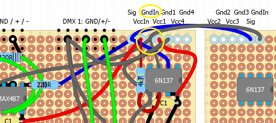
From the pin headers (the light blue circles), e.g. GndIn (upper yellow circle), I want to use 24AWG stranded wire to three other places on my protoboard (and one other), see the lower yellow circle.

Should I:

  1. Solder it like in the picture (one pin header with three wires soldered directly to the pin header); I can imagine it's a bit hard to solder three wires at the same time', maybe I should connect them first and solder them as one wire
  2. Make a vertical solder line until three pins below the GndIn pin header and solder each wire to a separate protoboard hole? However, this takes more space.
  3. Use another solution?

And I have actually the same questions for IC pins (not clearly shown in my example picture).

enter image description here

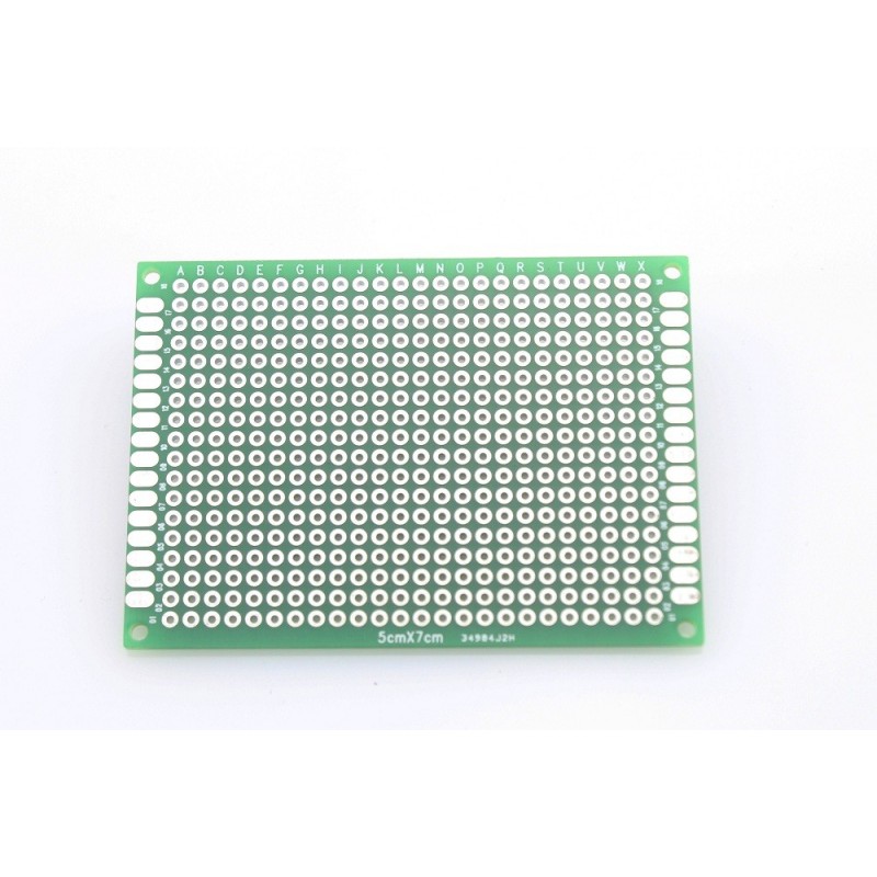
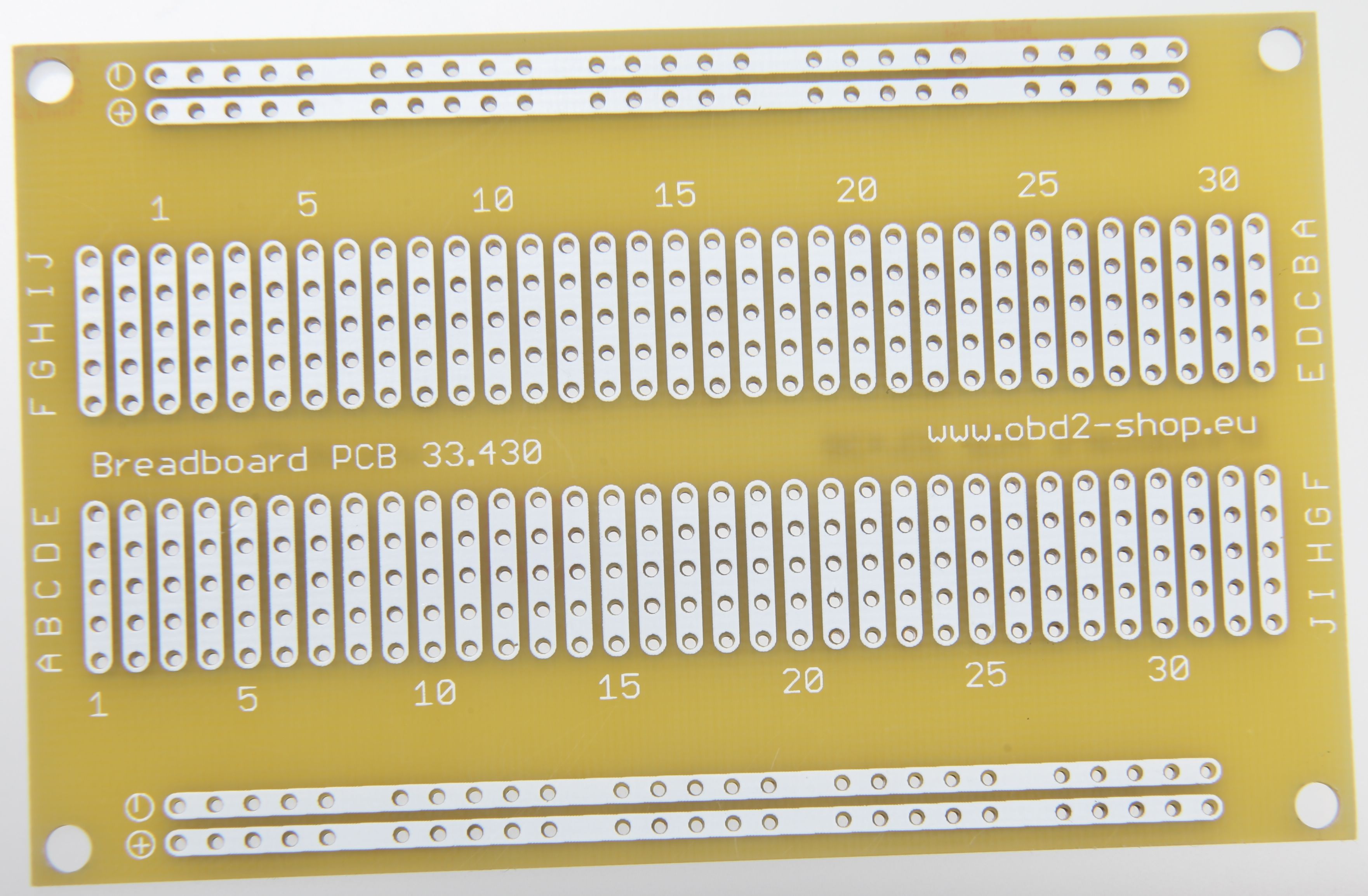
The protoboard I use is this type:

enter image description here

\$\endgroup\$
3
  • 2
    \$\begingroup\$ I'd rather run two stripped wires along those big pads on the sides for Vcc and Gnd and then use those pads for all other connections \$\endgroup\$
    – Maple
    Commented Sep 8, 2018 at 22:07
  • \$\begingroup\$ Well I could use GndIn on both sides, for VccIn I need only two wires. \$\endgroup\$ Commented Sep 8, 2018 at 22:12
  • \$\begingroup\$ I agree with @Maple, good practice is hard to beat. \$\endgroup\$
    – Solar Mike
    Commented Sep 8, 2018 at 22:15

3 Answers 3

1
\$\begingroup\$

With so many unused holes, you can be more creative in routing jumper wires to holes and expand the number common pads. Use the adjacent row if necessary.

  • Just route then as neat as you can, like a PCB layout without clusters of overlapped wires to avoid signal crosstalk and so solder joints can be clearly inspected.
  • It doesn't take any longer and if the wires are tight and routed tight or bent in right angles, it will look better. Snake wiring looks a bit suspect to prospective clients or employers. Flush rectangular routing without overlap looks well planned.
  • Trained assemblers will use instant adhesive dots sparingly to prevent long loose wires. ( as long as you know it is permanent)
  • Don’t use excess solder.
  • Get the right solder temp to allow you to solder in 2~3 seconds by preheating and then add solder wire in a smooth sequence then release.
  • Magnet wire is popular for thinner appearance and I just burn thru the varnish without inhaling or use a fume extractor.
\$\endgroup\$
8
  • \$\begingroup\$ It will be a bit hard to prevent overlaps, but I can do it better probably. I found out my wires are not solid, so right angles are impossible. I don't have clients btw, it's for myself (and for the band I play in, although they will probably never look inside the enclosure). \$\endgroup\$ Commented Sep 8, 2018 at 22:44
  • \$\begingroup\$ You can isolate rows at any hole by using a large drill bit in reverse in a variable speed drill. \$\endgroup\$
    – D.A.S.
    Commented Sep 8, 2018 at 23:03
  • 1
    \$\begingroup\$ Don’t forget to add test point labels. \$\endgroup\$
    – D.A.S.
    Commented Sep 8, 2018 at 23:05
  • \$\begingroup\$ I think drilling only applies to veroboard, I have protoboard where all holes are separate/isolated. With test point 'labels' you mean specific holes for testing I guess? \$\endgroup\$ Commented Sep 9, 2018 at 10:45
  • 1
    \$\begingroup\$ Never mind then. I use cut resistor wires as test points for scope probe. with Gnd pin nearby so probe ground can be very short with tip and clip removed for textbook waveforms. \$\endgroup\$
    – D.A.S.
    Commented Sep 9, 2018 at 12:27
1
\$\begingroup\$

My recommendation would be to only have one or two wires per pad and to daisy-chain your connections. It will make soldering easier and fault-finding less confusing.

On the other hand, if you can get three wires through the hole then there's nothing to stop you soldering all three.

enter image description here

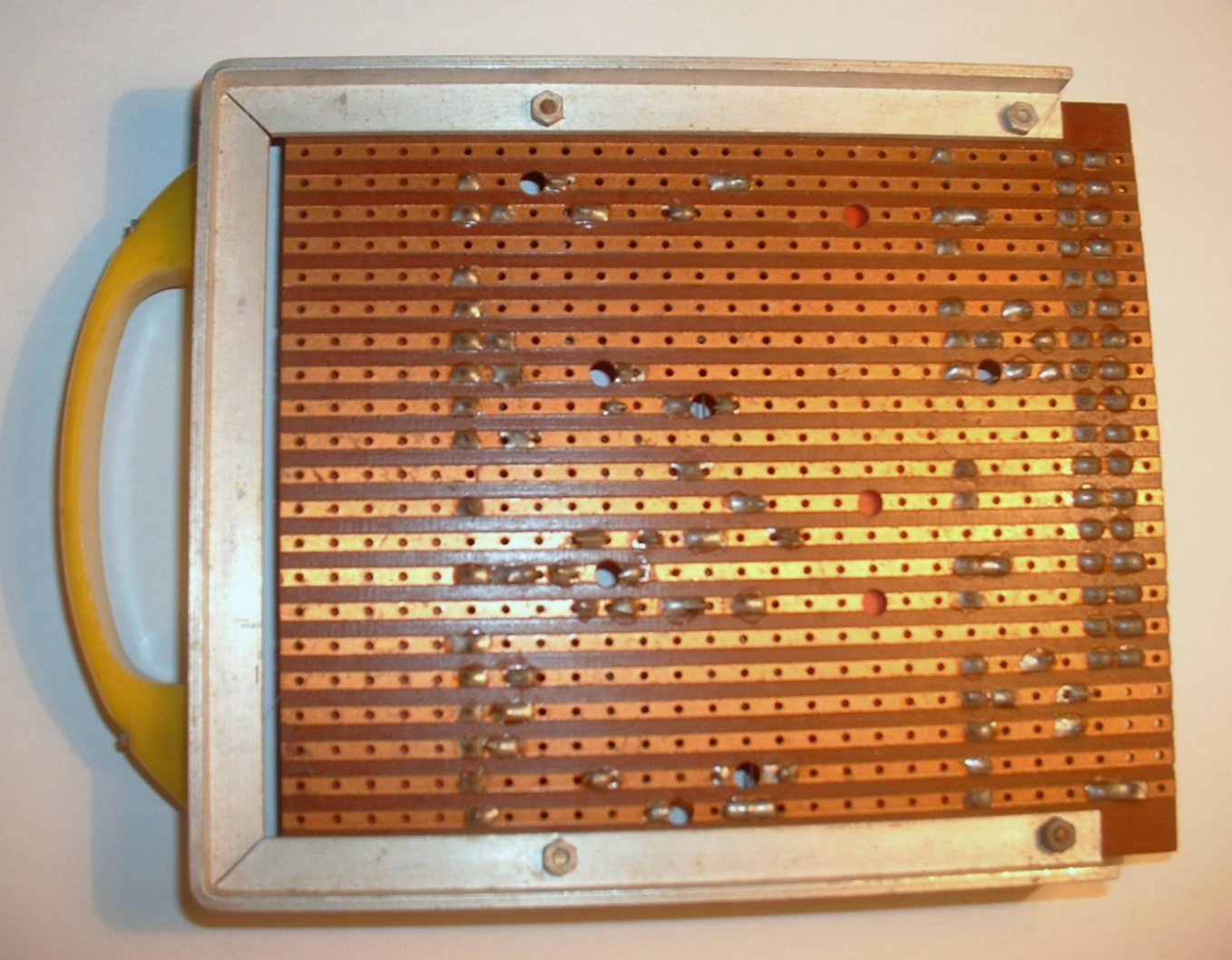
Figure 1. The underside of a project made on Veroboard. Note the neat solder joints and the holes drilled through to break the tracks. Image source: Wikipedia Veroboard.

enter image description here

Figure 2. A Vero tool is rotated by hand to remove copper around any hole thereby isolating the strips either side of that hole. This tool doesn't go right through the board as in Figure 1.

I've only used that type of board a couple of times and found it very difficult to make a good looking job. The standard strip-board or Veroboard is much simpler to use and very versatile.

enter image description here

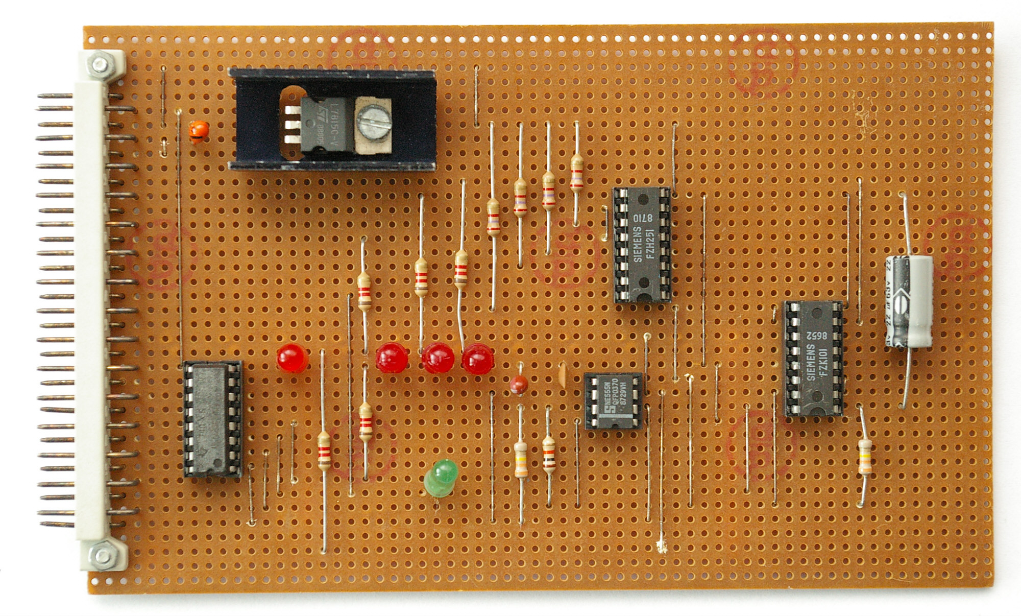
Figure 3. Rather neat circuits can be built on Veroboard if the components can be mounted perpendicularly to the direction of the copper tracks. Here there are no flying wires and all cross-connections are done with components or wire links. Image: Wikimedia Commons.

Other options such as solderless breadboard patterned versions exist also.

enter image description here

Figure 4. The breadboard-patterned version. Source: Wikimedia Commons.

There are many stripboard designers available which allow you to place components, links and break tracks. These can help to generate a plan for a very neat layout.

\$\endgroup\$
1
  • \$\begingroup\$ Just checked, it's not solid wire but stranded wire, and can only fit one wire through one hole, so better to use adjecent holes probably. I have a few veroboards, but I rather like the versatile ones since I want to use a small enclosure. \$\endgroup\$ Commented Sep 8, 2018 at 22:45
1
\$\begingroup\$

Unlike stripboard or the plastic breadboards, that board appears to have no connections between holes, so you have to make any between-hole connections yourself.

If you have a component inserted in a hole, it may be easier to solder the wire to that hole/component lead, rather than putting the wire in an adjacent hole, then trying to connect the two holes. (You'll find that solder will bridge large gaps where you don't want it to, but won't bridge a microscopic gap where you do want it to).

\$\endgroup\$
1
  • \$\begingroup\$ Guess I will use both ways, connecting to a component/hole when possible, otherwise use adjacent holes, or strip the wire on some places and continue 'branch' from there. \$\endgroup\$ Commented Sep 8, 2018 at 22:46

Your Answer

By clicking “Post Your Answer”, you agree to our terms of service and acknowledge you have read our privacy policy.

Not the answer you're looking for? Browse other questions tagged or ask your own question.