0
\$\begingroup\$

I purchased a Japanese transformer for a project I’m doing. It runs on 100VAC, not 120V, something I overlooked. Doing a quick search, Japan seems to use both 50/60Hz, based on the region.

It’s 30 years old and there’s no information about frequencies on it. I haven’t plugged it into anything yet.

How exactly will it respond to 120V? Here are some possible outcomes I’ve thought of with my limited knowledge.

  • It will initially work for a few minutes/seconds, then it will get fried and become useless
  • The output voltages/current will become stronger
  • Nothing will happen, and then it will get fried and become useless

Here’s a part of the schematic I’m using it for. It’s supposed to output +15V, -15V, and +5V.
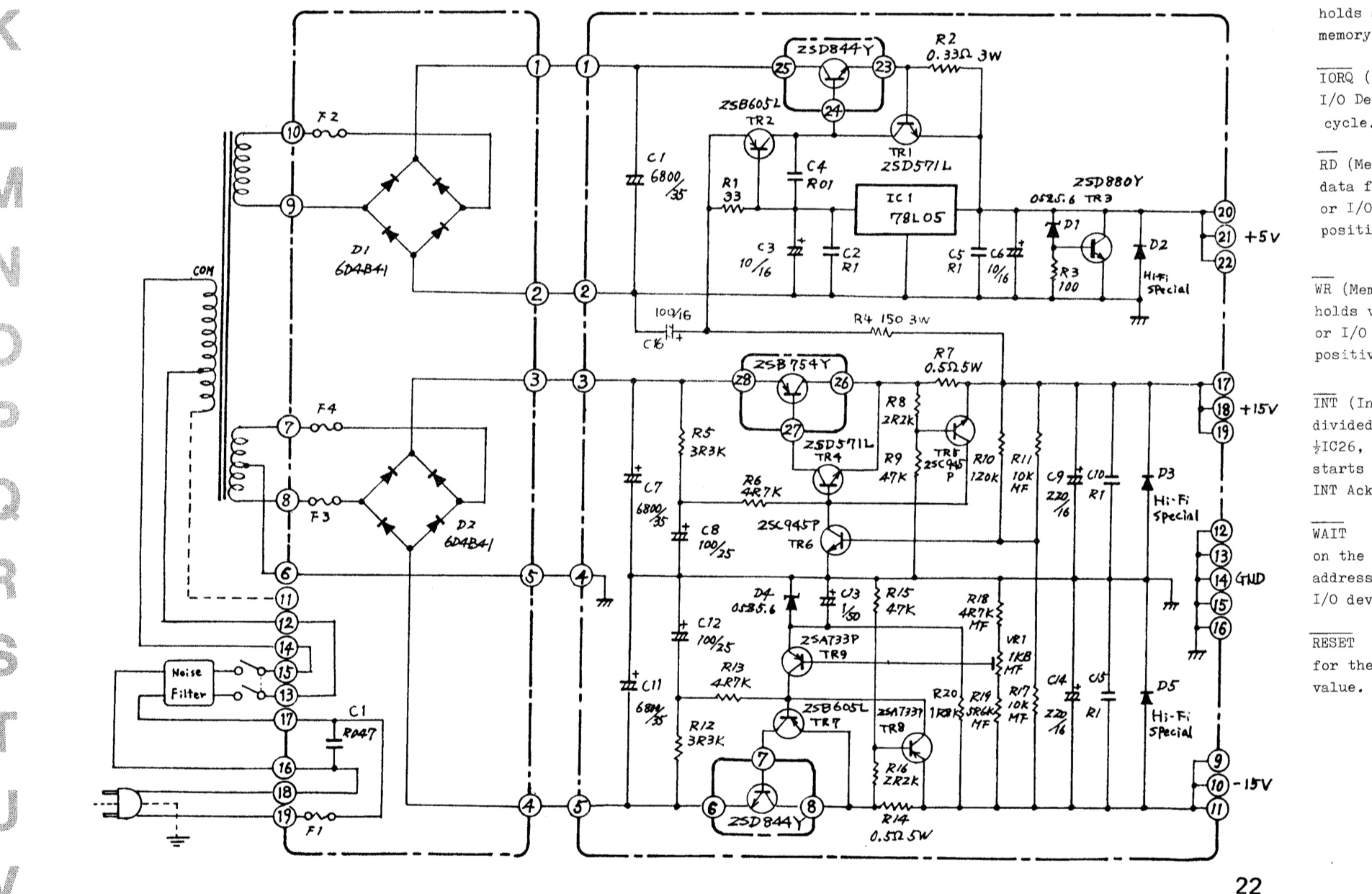
Schematic

\$\endgroup\$

2 Answers 2

3
\$\begingroup\$

It seems that the device was intended to run on two nominal voltages. It can be clearly seen that primary transformer has two taps: connecting terminals 11 and 12. I suggest you to remove the bridge between 13 and 12 and make a new connection to 13-11.

Then you connect to the mains and measure the AC voltage between 14 and 12. If it's nearly 100VAC, then you're done.

You can do also in opposite way. Disconnect the electronics part, connect the mains supply as is from schematics with a bridge 13-12, 14-15. You would get a step-up voltage between 14-11. If the tap at position 12 is designed for 100VAC and tap 11 for 120VAC, now when tap 11 is supplied with 120VAC you should get 144VAC on tap 12. That would be a proof that connecting 120VAC on tap 12 makes no difference for secondary voltage.

As user Charles said, if the transformer is designed for 100VAC/50Hz and you connect to 120VAC/60Hz, the flux denisty is still nominal. But the secondary voltages are going to increase for 20%.

\$\endgroup\$
2
\$\begingroup\$

If it is designed for 100 volts at 50 Hz, it will work fine on 120 volts at 60 Hz. With 120 volts at 50 Hz, the magnetization voltage will be 20 percent high. The transformer is probably designed to tolerate voltage that is 10 percent high. The result will be magnetization current that is a bit more than 10 percent more than the transformer is designed for. The iron losses will be higher than normal, so the transformer's operating temperature will be higher than normal. If the load current is lower than the rated current, that will reduce the copper losses and compensate for the increased iron losses to some extent. You will not notice the difference in a few minutes. It will take the transformer longer than that to reach a steady operating temperature.

The schematic shows a dual-voltage primary. Perhaps it is designed for either 100 volts or 120 volts. Connect 100 volts across the entire primary and measure the voltage between the unused connection and the other end of the winding.

\$\endgroup\$
5
  • \$\begingroup\$ So I don’t need to take any precautions? Is it going to be degraded faster? It’s not made anymore and finding another one with the same specifications would be difficult. \$\endgroup\$
    – ToastHouse
    Commented Oct 27, 2018 at 17:40
  • 1
    \$\begingroup\$ @ToastHouse: It won't fry itself immediately. If you're that worried, leave the secondary unconnected, then go through the following: first, connect the primary to 120V through an ammeter. Compare the amps you read with the rating -- it should be no more than 10 or 20% (depending on how cheap it is). If it doesn't immediately suck huge currents, then leave it connected for a minute, checking to see how warm it's getting. Check it every 30 seconds at first, then every minute or two. If you can leave it connected for 30 minutes and it's only a bit warmer than the room, you're fine. \$\endgroup\$
    – TimWescott
    Commented Oct 27, 2018 at 18:36
  • 1
    \$\begingroup\$ Charles, you've addressed the transformer effects nicely. Since the unregulated DC will be higher with 120v substituted for 100v, DC output load current should be de-rated, since those series-pass power transistors run hotter...giving a more-complete answer regarding heat. \$\endgroup\$
    – glen_geek
    Commented Oct 27, 2018 at 19:49
  • \$\begingroup\$ Without me having to open another question, what do you think the capacitor values such as C1 in the bottom left corner mean? The others make sense to me, but some start with “R” and have confusing numbers following them. I don’t see a voltage, and don’t want to get it wrong. \$\endgroup\$
    – ToastHouse
    Commented Oct 28, 2018 at 1:58
  • 1
    \$\begingroup\$ I expect the capacitors with no voltage marked are capacitor types like ceramic for which the minimum voltage for which they are manufactured are high enough that it is not of much concern. Beyond that, someone else could provide better answers about circuit details. I was not paying much attention to the question details that are not related to the transformer question. Make sure to pay attention to what glen_geek and Marko Bursic wrote. \$\endgroup\$
    – user80875
    Commented Oct 28, 2018 at 3:26

Your Answer

By clicking “Post Your Answer”, you agree to our terms of service and acknowledge you have read our privacy policy.

Not the answer you're looking for? Browse other questions tagged or ask your own question.