1
\$\begingroup\$

I was asked to find the Thevenin-Norton equivelant, and I got stuck on some things that I can't quite understand. I don't know if i need to be more specific.

enter image description here

enter image description here

enter image description here

What's wrong with the following? enter image description here

And why isn't this allowed?

enter image description here

\$\endgroup\$
2
  • 2
    \$\begingroup\$ You definitely need to be more specific about the first part of this question, but I can answer the "why can't you do this" parts: you can't do that because your A and B nodes are no longer the same after doing it; \$V_{AB}\$ is different in the first one than the second. This holds for both of the cases you asked about. \$\endgroup\$
    – Hearth
    Commented Dec 12, 2018 at 2:15
  • 1
    \$\begingroup\$ You haven't obeyed the rules for parallel and series connections. For example, two resistors are in series if there's nothing else connected to their junction. So in your final two diagrams the 6/48/2 resistors are not in series because A and B are connected to the junctions. \$\endgroup\$
    – Chu
    Commented Dec 12, 2018 at 9:51

1 Answer 1

2
\$\begingroup\$

Every circuit transformation that you do must give a result at the "A & B" terminals indistinguishable from the final Thevenin or Norton equivalent: for this circuit arrangement you must have an open-circuit output voltage of 48V, and a short-circuit current of 4A at the A & B terminals for every step.

Your attempted circuit transformation gives an open-circuit voltage of 96V and a short-circuit current that is infinite:

schematic

simulate this circuit – Schematic created using CircuitLab


Another problem - I could combine 48 ohms and 2A current source this way, which would also be wrong:

schematic

simulate this circuit
The primary reason why these reductions don't work is those pesky output terminals A and B don't allow you to do transformations at that end...a Thevenin or Norton equivalent circuit has TWO terminals, not FOUR.

However, the 48 ohm resistor can combine with the 2A current source to form a Thevenin equivalent in the following way, that is correct:
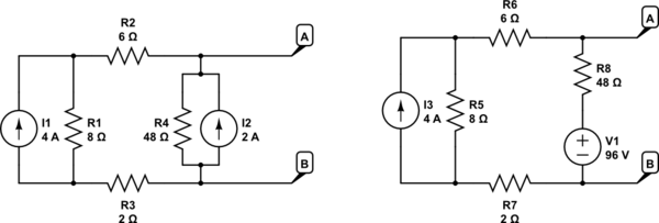
schematic

simulate this circuit

\$\endgroup\$
8
  • \$\begingroup\$ I think i understand the current source to voltage source problem.But to be fully answered i have to ask something else... Is the current source-resistor the same with a voltage source and the resistor on the same cable and with a voltage source on one cable and the resistor on the upper right or left cable?Here is what i mean -> prntscr.com/ltxz12 . Also in a text i have what i fully udnerstood about the problem. But i still dont get how the 3 resistor combination is wrong. How does it change the A,B(can i know it before hand, without testing it?), or is it because they arent inseries? \$\endgroup\$ Commented Dec 12, 2018 at 10:39
  • \$\begingroup\$ Wrong picture . Heres what i mean prntscr.com/lty1u7 \$\endgroup\$ Commented Dec 12, 2018 at 10:45
  • \$\begingroup\$ On combining 2,6,48 ohm resistors: That would only work if you're assured that current is the same through all three. That's not the case. I've edited the answer to correct voltage polarity, and added a kosher way of transforming the 2A,48 ohm into a Thevenin equivalent. \$\endgroup\$
    – glen_geek
    Commented Dec 12, 2018 at 15:26
  • \$\begingroup\$ so my picture is wrong(the above one^)?the voltage source and resistor on the same cable are diffrent than the voltage source and resistor on the upper left or right cable?Please read the text in the printscreen if u can understand \$\endgroup\$ Commented Dec 12, 2018 at 15:35
  • \$\begingroup\$ Are the 2 = on my picture prntscr.com/lty1u7 true or false to begin with? \$\endgroup\$ Commented Dec 12, 2018 at 15:36

Your Answer

By clicking “Post Your Answer”, you agree to our terms of service and acknowledge you have read our privacy policy.

Not the answer you're looking for? Browse other questions tagged or ask your own question.