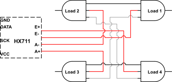
I have an hx711 ADC module with 4 50kg load sensors wired in a wheatstone bridge (for a maximum load of 200kg).
When I apply load to the sensors, the resulting values for increasing weights appear to be non-linear, which is the opposite of what I would expect.
I've tried connecting the module to both a Raspberry Pi and a Wemos d1 mini (esp8266) and get the same results each time. I've also tried rewiring the bridge in different configurations, but only one gives any results.
The results I see are as follows:
0kg: 498,000
1kg: 500,000
10kg: 505,000
25kg: 530,000
100kg: 550,000
As you can see the 'correction factor' to grams is approximately:
result / 500 / weight in kg
Is this likely to be a fault with the ADC module, an issue with wiring, or something else I'm doing wrong?
The ADC module spec: https://cdn.sparkfun.com/datasheets/Sensors/ForceFlex/hx711_english.pdf
The load sensor spec: https://ae01.alicdn.com/kf/HTB1ZDtuKXXXXXX9XVXXq6xXFXXXI/201492522/HTB1ZDtuKXXXXXX9XVXXq6xXFXXXI.jpg
Wiring schematic (sorry for poor quality - not used the tool before!). The load cells are connected:
1: red -> E-, Black -> 2, White -> 3 2: red -> A-, Black -> 1, White -> 4 3: red -> A+, Black -> 4, White -> 1 4: red -> E+, Black -> 3, White -> 2

simulate this circuit – Schematic created using CircuitLab
The voltage in (VCC) is nominally 5V - measured at 5V on RPi, and 4.8V on Arduino. The Excitation voltage is always 4.17V, regardless of VCC. I don't have accurate enough multimeter to read A+/-.
