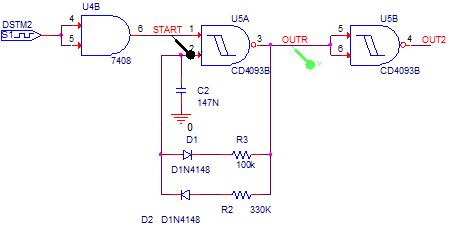
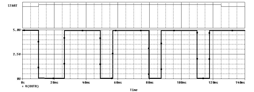
Why does the triggered astable in the next figure have the duration of the logical component "0" of the first pulse lasting 2 times the logical component "0" duration of the next pulses (see the answer below)? Are there any triggered astable that have the same pulse duration even from the moment of triggering?
1 Answer
The Schmitt trigger input high is approximately 2/3 supply and input low is 1/3 supply. On turn-on C2 is completely discharged so it will take approximately \$ \tau = RC \$ seconds to reach the high threshold causing U5A to switch. C2 then starts to discharge but now only takes half the time to reach the low threshold. This results in the remainder of the pulses having a shorter period.

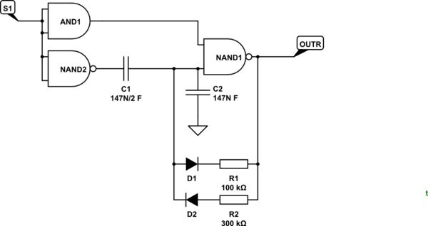
simulate this circuit – Schematic created using CircuitLab
Figure 1. Addition of C1 will "kick" the junction of C1/C2 to 2/3 V+ when S1 is turned on.
Try the addition of C1 as shown in Figure 1.
How it works:
- With S1 off OUTR is high and C2 is charged to V+. NAND1 won't switch until the voltage on C2 falls to 1/3 V+.
- When S1 is turned on NAND2 switches low pulling C1 low. Since C1 is half the value of C2 the junction should instantly fall to 2/3 supply eliminating the extra delay on the first cycle.
Note that the time constant is now R(C1 + C2). If you need to keep the same output frequency then reduce C2 by 33% and set C1 to half that value.
I've never built this. Let me know how if it works.
From the comments.
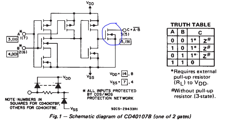
No, not working. I used CD40107B as NAND,
That was an unfortunate choice. Have a look at the datasheet.
Figure 2. The CD40107B is open drain output. It can't pull high.
Since the 40107 output stage can't pull C1 high the left side of C1 never charges up to V+. As a result the switching of NAND2 does nothing. You need a push-pull output stage or add a pull-up resistor. 1k should be OK.
-
\$\begingroup\$ OK, I understand now WHY this happen. Can I avoid this, i.e. are there any triggered astable that have the same pulse duration even from the moment of triggering? \$\endgroup\$ Commented Jan 4, 2019 at 10:56
-
-
\$\begingroup\$ @ Transistor. No, not working. I used CD40107B as NAND, C1=50nF, C2=100nF. The same problem: first pulse has double period; simulation on PSPICE-ORCAD \$\endgroup\$ Commented Jan 4, 2019 at 11:46
-
-
\$\begingroup\$ @ Transistor. OK, with CD4011 worked better: first pulse has 19ms period, the others 15.4ms. More improvements? Thanks!! \$\endgroup\$ Commented Jan 4, 2019 at 12:07


