11
\$\begingroup\$

I've recently grown interested in electronics and robotics, so I wanted to move my contraption using a servo motor. A 555 chip creates a PWM signal for servo for positioning, and I control the servo with a variable resistor.

I'm sure it will be able to move my contraption with ease, but I'm not comfortable putting 3 A through the breadboard (which would happen if the servo stalled).

Would something like the following work?

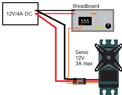
Picture showing how to route power around the breadboard

I believe this would route power required by the servo around the breadboard so breadboard would only work with the current required for controlling the servo motor, for creating PWM.

\$\endgroup\$
1
  • 1
    \$\begingroup\$ Be aware of I*R voltage drop in the high-current Ground wire. If at least 2 or 3volts, the 555 signal may not be "high" enough to turn on the motor. \$\endgroup\$ Commented Jan 30, 2019 at 3:51

1 Answer 1

20
\$\begingroup\$

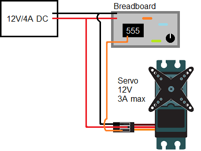
You are correct, this will avoid passing a heavy current through the breadboard.

Make sure the wires that go from the power supply to the motor are capable of carrying the maximum expected current. Ideally take these wires separately all the way back to the power supply and run another pair of wires from the power supply to the breadboard.enter image description here

\$\endgroup\$
5
  • 5
    \$\begingroup\$ For additional safety, you can put some sort of overcurrent protection device at the point where the power cables connect to the breadboard. Voltage regulation with transient spike suppression is probably even more important; motors can generate nasty transients when they start and stop moving. (Make sure the power supply is rated to handle a 3A motor specifically, too.) \$\endgroup\$
    – zwol
    Commented Jan 29, 2019 at 19:10
  • 1
    \$\begingroup\$ Add an R+C filter into the VDD to the breadboard: 10 ohms and 100uF, to help hold the Breadboard voltage steady during motor spikes. \$\endgroup\$ Commented Jan 30, 2019 at 3:53
  • \$\begingroup\$ @zwol should I put fuses on both power and ground wires (connecting to the breadboard) and also maybe a diode on ground (to make sure the 'amps' flow the right way - to ground)? \$\endgroup\$ Commented Jan 30, 2019 at 8:03
  • \$\begingroup\$ @analogsystemsrf I believe R (10 ohms) should be put on the power line (red in schema) and C (100uF) between power and ground. And this should be done before connecting to breadboard, correct? \$\endgroup\$ Commented Jan 30, 2019 at 8:06
  • 1
    \$\begingroup\$ @FourJoltsYouSummerPulse I'm sorry, I don't know how to design overcurrent/voltage protection circuits in detail, I only know you probably need one in this application. \$\endgroup\$
    – zwol
    Commented Jan 30, 2019 at 16:02

Your Answer

By clicking “Post Your Answer”, you agree to our terms of service and acknowledge you have read our privacy policy.

Not the answer you're looking for? Browse other questions tagged or ask your own question.