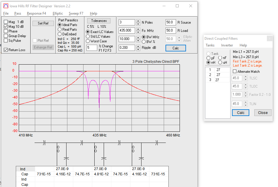
When you get unrealisable component values in your theoretical design, it's a sign that you need to change your filter topology.
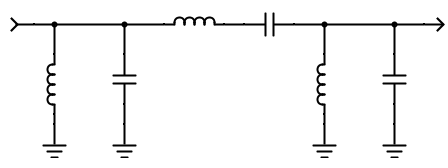
That second stage series resonant tuned circuit has an impedance that's too high, which means a series capacitance that's too small. Amongst your options are (depending on the particular frequencies)
a) Reduce the impedance of that series LC
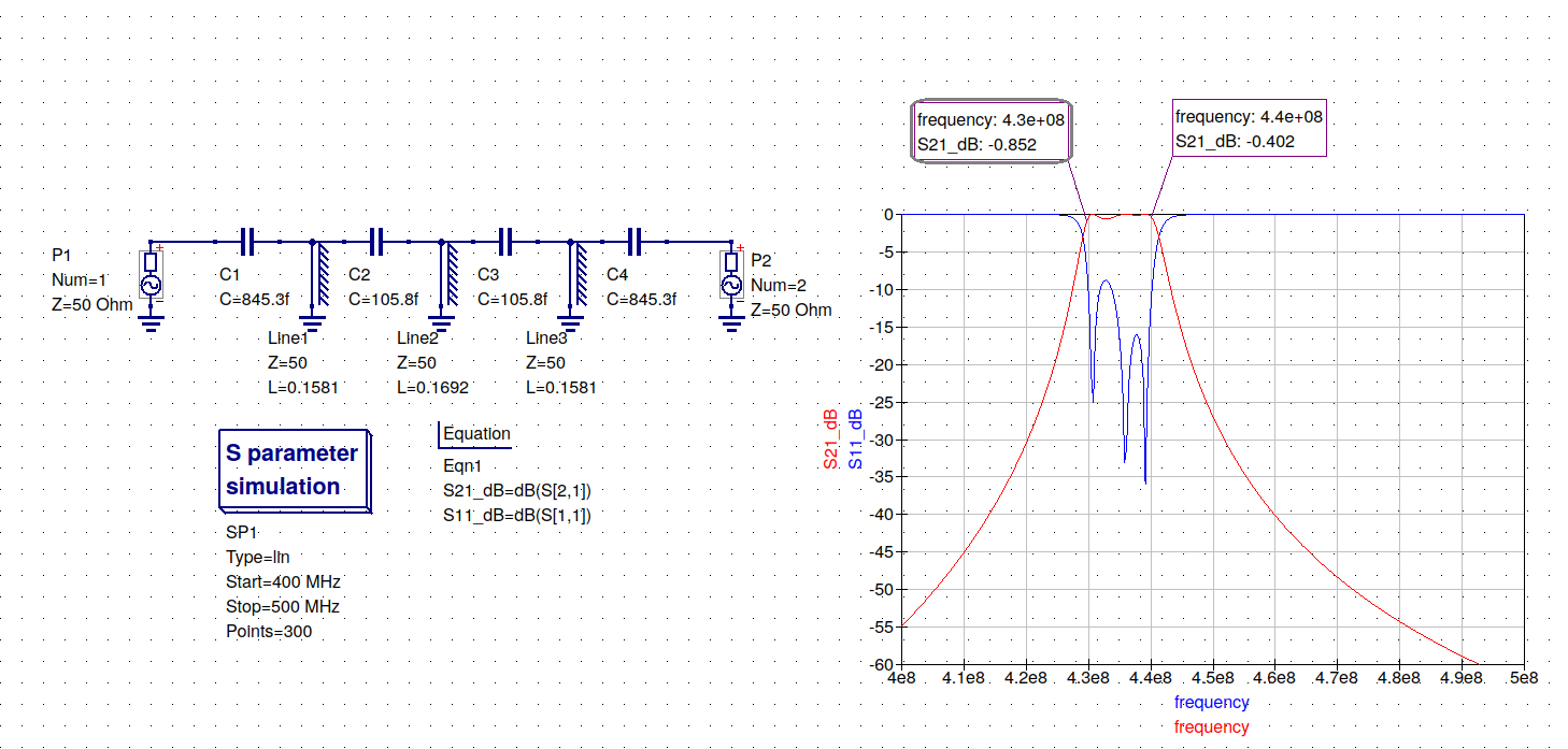
b) Turn it into a shunt LC, and couple it to the other sections some other way
c) Implement it as a different type of resonator
a) Reduce the impedance
The sections before and after the problem section are shunt LCs. By implementing the Ls as tapped inductors, or the Cs as a series combination of two capacitors, you can create tap points at a much lower impedance. A 10:1 voltage ratio creates a 100:1 impedance ratio, and should be quite practical at 400MHz. This would allow you to increase the C value by up to 100 times, with a corresponding decrease in L. This is such a common problem that most reputable filter design tools will include an impedance scaling option in the design.
b) Design an all shunt resonator filter
Once you have a line of resonators, you have to couple them somehow. Amongst the options are 'top coupled', using a high impedance (but now far less critical value) series C or series L between sections; 'bottom coupled' where the two adjacent resonators share a very low impedance; 'field coupled' where the adjacent Ls are fabricated to include some mutual coupling. Most reputable design tools will facilitate a bandpass filter design based on coupled sections, the design simply produces a list of centre frequencies, and the mutual coupling between them
c) A different resonator type
The component scaling problem becomes more severe as the width of the passband decreases. Replacing series LC component resonators with a resonator component like a crystal or ceramic resonator can work.


