1
\$\begingroup\$

I am going to try to build a Butterworth LC bandpass filter. However, using some online calculators result in some very low value capacitors (sub-1pF).

I am thinking that the performance will not be optimal because even the stray capacitance of the PCB traces (I want to use prototype boards) will be higher than that value.

Is that true? If it is, how do I build a RF filter easier with standard value inductors and capacitors?

EDIT: I want to build a simple LC bandpass filter for 430-440MHz, trying online calculators like this shows for first element is shunt, the capacitance of second element (which is in series) is 0.091pF. (Center Freq=435MHz, BW=10M, Z=50Ohm, Order=4, Shunt First)

Shunt-first Butterworth LC BPF

\$\endgroup\$
6
  • \$\begingroup\$ I've seen cases where they design the traces specifically to get a targeted value of capacitance or inductance from the parasitics (like a trace that just looks like a square-wave). \$\endgroup\$
    – DKNguyen
    Commented Apr 18, 2019 at 0:07
  • 2
    \$\begingroup\$ What frequency and impedance are you designing for. Edit your question to show a schematic, please. \$\endgroup\$
    – TimWescott
    Commented Apr 18, 2019 at 0:07
  • \$\begingroup\$ @Toor For a prototype with prototype boards, is there any way to build such filters with ease? It seems that the low value caps really impedes hobbyist like me. @ TimWescott Sure. \$\endgroup\$ Commented Apr 18, 2019 at 0:10
  • 1
    \$\begingroup\$ Above a few hundred MHz helical resonators are often coupled one-to-the-next via an aperture in the common wall(s) (instead of a sub-picofarad capacitor). In any case, a new design will require instrumentation to tune properly. Those tiny-pf capacitors can be hand made: two wires close together for example. The other problem you face is impedance matching ends to 50 ohms. \$\endgroup\$
    – glen_geek
    Commented Apr 18, 2019 at 0:37
  • 1
    \$\begingroup\$ you might be interested that Johanson Technology make these in LTCC 0805 SMD chips 1.9dB IL which have advantages in size, cost <$0.50 digikey.com/product-detail/en/johanson-technology-inc/… tolerances are important digikey.com/en/ptm/j/johanson-technology/… \$\endgroup\$
    – D.A.S.
    Commented Apr 18, 2019 at 2:50

3 Answers 3

3
\$\begingroup\$

When you get unrealisable component values in your theoretical design, it's a sign that you need to change your filter topology.

That second stage series resonant tuned circuit has an impedance that's too high, which means a series capacitance that's too small. Amongst your options are (depending on the particular frequencies)

a) Reduce the impedance of that series LC
b) Turn it into a shunt LC, and couple it to the other sections some other way
c) Implement it as a different type of resonator

a) Reduce the impedance

The sections before and after the problem section are shunt LCs. By implementing the Ls as tapped inductors, or the Cs as a series combination of two capacitors, you can create tap points at a much lower impedance. A 10:1 voltage ratio creates a 100:1 impedance ratio, and should be quite practical at 400MHz. This would allow you to increase the C value by up to 100 times, with a corresponding decrease in L. This is such a common problem that most reputable filter design tools will include an impedance scaling option in the design.

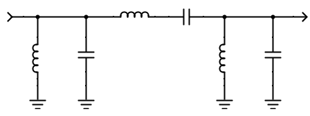
b) Design an all shunt resonator filter

Once you have a line of resonators, you have to couple them somehow. Amongst the options are 'top coupled', using a high impedance (but now far less critical value) series C or series L between sections; 'bottom coupled' where the two adjacent resonators share a very low impedance; 'field coupled' where the adjacent Ls are fabricated to include some mutual coupling. Most reputable design tools will facilitate a bandpass filter design based on coupled sections, the design simply produces a list of centre frequencies, and the mutual coupling between them

c) A different resonator type

The component scaling problem becomes more severe as the width of the passband decreases. Replacing series LC component resonators with a resonator component like a crystal or ceramic resonator can work.

\$\endgroup\$
0
\$\begingroup\$

@Neil_UK is right.

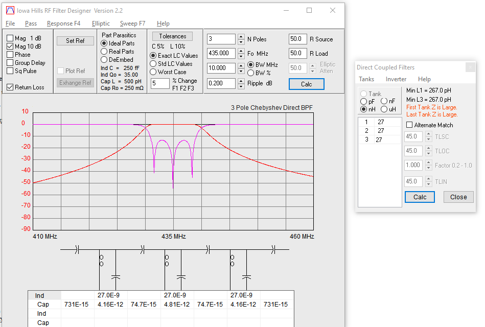
Specifically, I'd use a direct coupled filter with shunt resonators (b). In practice you'll have to tune the values of the inductors manually (because of the influence of the tolerance, parasitics, PCB,... in the filter response).

You may use the following tool for the first approach: http://www.iowahills.com/9RFFiltersPage.html

enter image description here

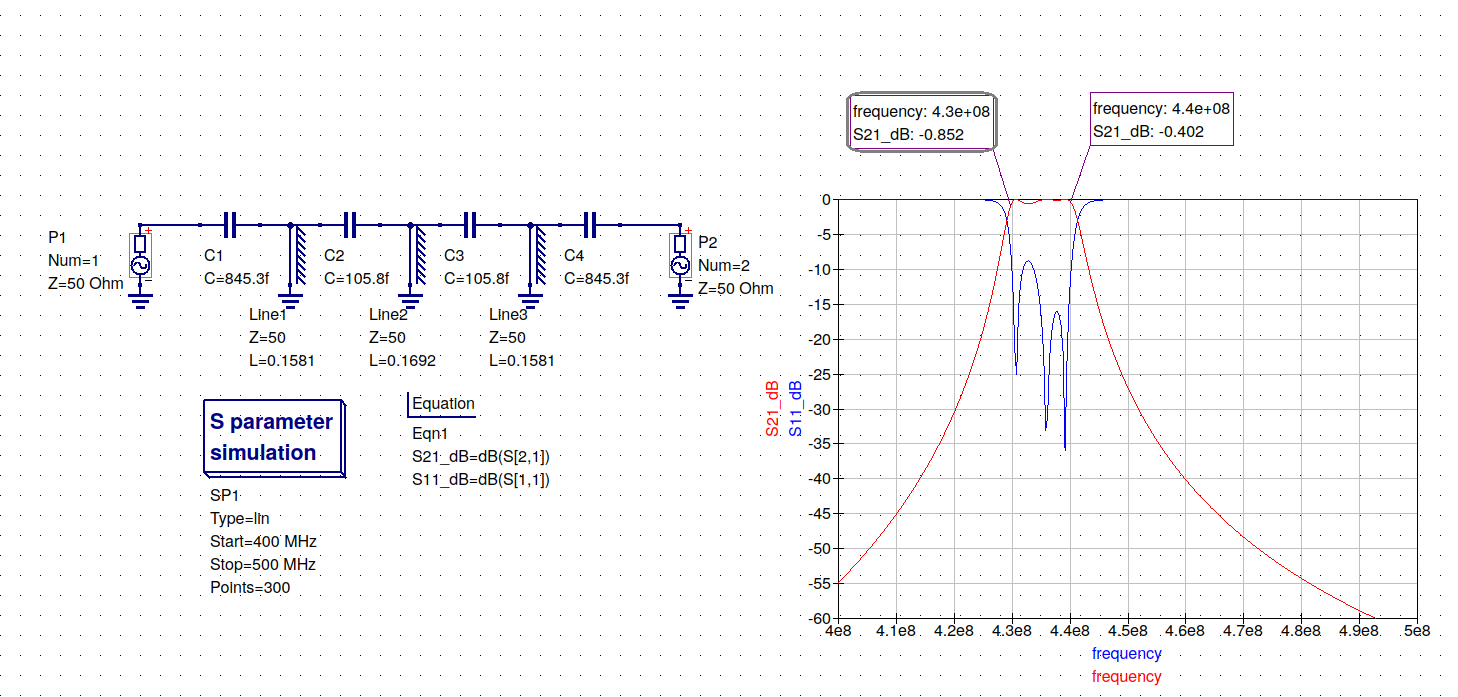
EDIT: Another circuit topology that may be of interest for your application is the capacitively coupled transmission line resonator filter. See 1. But, of course, the transmission line resonators are quite big at 435 MHz...

enter image description here

1 Microwave Engineering. David Pozar. 4th Edition. Section 8.8, page 437

\$\endgroup\$
2
  • \$\begingroup\$ The series C is 74.7fF, which is still ridiculously small... \$\endgroup\$ Commented May 12, 2019 at 8:46
  • \$\begingroup\$ Obviously, you won't find a 74fF chip capacitor. Capacitively coupling occurs because of the proximity of both resonators. In practice, the nature of the coupling is usually mixed because of the mutual inductance of the shunt inductors. \$\endgroup\$
    – user162437
    Commented May 12, 2019 at 18:19
-2
\$\begingroup\$

The sub-pf caps can effectively be ignored. This will result in dc coupling, but any hi Q capacitor can effectively be used to decouple the circuit. Try your design at this url and note the difference... they're just not used.

https://rf-tools.com/lc-filter/

Note when building a circuit like this pc capacitance does play a part - if prototyping, the board should be built using isolated "island" pads soldered over the ground plane, as in Using copper clad for RF projects

\$\endgroup\$
4
  • \$\begingroup\$ Tried the link you gave, and for the same inputs (3rd-order Butterworth, 430-440 MHz passband) it does give a result using an 84 fF capacitor. And this isn't just dc blocking. It's meant to resonate with the series inductor to give the desired bandpass response. \$\endgroup\$
    – The Photon
    Commented Apr 18, 2019 at 1:54
  • \$\begingroup\$ Of course the cap is meant to resonate in the circuit. But for such a low value in the series circuit, a higher value (say, a common value like 2.2pf) will only result in a slightly lower rolloff on the bottom end of the spectrum, thus a slightly lower overall Q. \$\endgroup\$ Commented Apr 18, 2019 at 2:33
  • \$\begingroup\$ Here is what LTSpice says happens if you change that capacitor to 2.2 pF. Passband insertion loss changes from ~0 dB to ~30 dB. That's not just "a slightly lower roll-off on the bottom end of the spectrum" or "slightly lower overall Q". \$\endgroup\$
    – The Photon
    Commented Apr 18, 2019 at 2:38
  • \$\begingroup\$ It's a lower overall Q. Thus, as I said before, omit the pole2 capacitor and decouple the circuit outside the filter. This discussion is clearly hobbyist related - if you're concerned about having an "ideal" 432 MHZ passband filter, that's why mini circuits exists. \$\endgroup\$ Commented Apr 18, 2019 at 4:33

Your Answer

By clicking “Post Your Answer”, you agree to our terms of service and acknowledge you have read our privacy policy.

Not the answer you're looking for? Browse other questions tagged or ask your own question.