1
\$\begingroup\$

If possible, what are calculations and precautions involved in making a simple transformer without core? The only purpose of this transformer is to trigger an opto-coupler for zero-crossing detection of mains supply.

schematic

simulate this circuit – Schematic created using CircuitLab

\$\endgroup\$
8
  • 2
    \$\begingroup\$ Why do you want to avoid a core? For a mains-connected transformer a core will be necessary for a practical design. \$\endgroup\$
    – John D
    Commented May 1, 2019 at 14:52
  • \$\begingroup\$ @john-d: space (Lining Box) and cost. \$\endgroup\$
    – M.Youcef
    Commented May 1, 2019 at 15:01
  • 1
    \$\begingroup\$ This transformer would be big as your house. \$\endgroup\$ Commented May 1, 2019 at 15:13
  • 2
    \$\begingroup\$ Any mains connected transformer will need to have a primary inductance of a henry or so so, if air-cored, think about how many turns are needed. \$\endgroup\$
    – Andy aka
    Commented May 1, 2019 at 15:16
  • 1
    \$\begingroup\$ You may need to use something like this or this. \$\endgroup\$
    – jonk
    Commented May 1, 2019 at 17:21

2 Answers 2

4
\$\begingroup\$

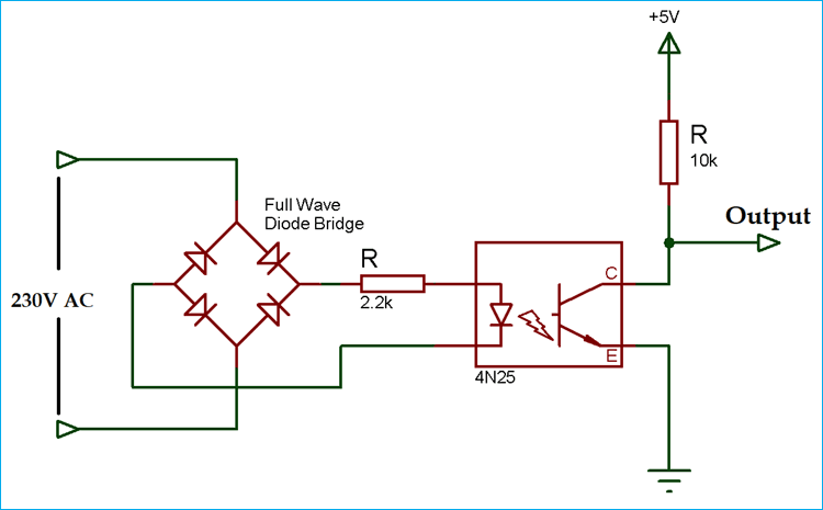
Since you said that it didn't need to be isolated, maybe something like this would work:

enter image description here

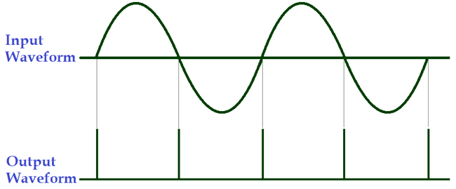
Output looks like this: enter image description here

If you are on 120Vac, then change the 2.2k to ~1.1k.
Again, beware that the left hand side is not isolated from the mains.

Source: https://circuitdigest.com/electronic-circuits/zero-crossing-detector-circuit-diagram

UPDATE: Per the other answer, looks like some caveats are in order to the sourced circuit as given.

  1. As pointed out, the power will be quite high in the 2.2kΩ resistor. Since the input waveform is NOT filtered with a capacitor The correct equation for the current is the average of the peak voltage divided by the resistance: $$ I=\frac{230V*\sqrt{2}*63\%}{2.2kΩ} = 94mA$$ The power is then $$P=94mA^2*2.2kΩ=19W$$ This is quite high for most circuits. It does work, but we can do much better.

    The opto coupler is well specified down below 1mA, so: $$ I=\frac{230V*\sqrt{2}*63\%}{200kΩ} = 1.0mA$$ The power is then $$P=1mA^2*200kΩ=214mW$$ Much better!

  2. As for the time that the input voltage can cause an output pulse: The forward voltage drop at 1mA is 0.9V, so $$325V*sin(2\pi*50*t) \text{ where} -8.82us < t < +8.82us$$ Thus 17.6us is the time the pulse is output. Plenty of time to detect it! And will look very very similar to the wave form image above.

\$\endgroup\$
3
  • \$\begingroup\$ There are a few things wrong with this answer. See electronics.stackexchange.com/a/576994/124114 \$\endgroup\$
    – handle
    Commented Oct 9, 2022 at 10:03
  • \$\begingroup\$ @handle updated to address the concerns. \$\endgroup\$
    – Aaron
    Commented Oct 10, 2022 at 18:24
  • \$\begingroup\$ This also overlooks the speed of the phototransistor, which, especially at low drive currents, will be ponderous (>20µs). A good solution is a depletion mode FET like LND150 as a current limiter, both saving power dissipation and improving response time. \$\endgroup\$ Commented Oct 11, 2022 at 0:51
2
\$\begingroup\$

The above circuit by Aaron is NOT possible! The sine wave graph is also not correct!!

Reason, simple.

current at 2.2K resistor is 230*√2/2200 =0.1478496 A
Heat produced at 2.2K resistor is 0.1478496^2 * 2200 =48 WATT !!!

The graph of zero cross is not correct either, because diode generally drops 0.75v, at positive cycle of AC zero cross will occur at 0.75v earlier and negative cycle will zero cross 0.75v later.

The time can be calculated as (0.75/((230x√2x2x3.14x50)=7.34 micro second

Since it is about zero crossing, so it does not work. And it's devastating for a novice.

\$\endgroup\$
3
  • \$\begingroup\$ Thanks for keeping me honest. I've updated my answer with full analysis to show the corrected/workable values. \$\endgroup\$
    – Aaron
    Commented Oct 10, 2022 at 18:22
  • \$\begingroup\$ It's possible to adjust the delay by adding a small capacitor across the resistor. And it might be better to put the resistor ahead of the diode bridge, to the mains. Also, two 100k resistors, one on each leg, may be safer. Many resistors are not rated for 400V as needed here. \$\endgroup\$
    – PStechPaul
    Commented Oct 10, 2022 at 19:43
  • \$\begingroup\$ That's peak current. Average power is half or 24W. \$\endgroup\$ Commented Oct 11, 2022 at 0:52

Your Answer

By clicking “Post Your Answer”, you agree to our terms of service and acknowledge you have read our privacy policy.

Not the answer you're looking for? Browse other questions tagged or ask your own question.