2
\$\begingroup\$

I need to generate a negative voltage of approximately -12V from a 12V power supply. I read about ICL7660A that performs supply voltage conversions from positive to negative for an input range of +1.5V to +12.0V resulting in complementary output voltages of -1.5V to -12.0V. I need it to feed NE5532 OPAMPs symmetrically to perform a low pass filter, to transform a square wave into a sine wave.

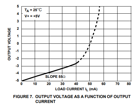
However, I looked at the ICL7660A datasheet and it does not explain very much about current capacity, just a graph (datasheet Figure 7) of load current vs. output voltage. In that graph, the ICL7660A is fed by a 5V power supply and the load current seems to reach zero when output voltage reaches -5V.

Figure 7 from ICL7660A datasheet - load current vs. output voltage

(Image source: Figure 7 from ICL7660A datasheet)

I don't know exactly how much current will be required, but there are 4 NE5532 OPAMPs. I suppose that something near 50 mA is enough, no more than that.

So, I was thinking: I need -12V from a 12V power supply, is it possible? If not, is there a better approach?

\$\endgroup\$
5
  • 1
    \$\begingroup\$ How much load current do you need from the -12V supply? \$\endgroup\$ Commented May 6, 2019 at 13:41
  • 1
    \$\begingroup\$ Renesas ICL7660A seems to accommodate a 12V supply. Many ICL7660 from various IC suppliers won't go that high. Be aware that the output appears to have about 60 ohms series resistance. Do any of your NE5532 op amps drive low impedance loads requiring much peak current? \$\endgroup\$
    – glen_geek
    Commented May 6, 2019 at 13:48
  • 1
    \$\begingroup\$ If you choose wisely your R values and OA you could go <1mA \$\endgroup\$
    – D.A.S.
    Commented May 6, 2019 at 14:09
  • \$\begingroup\$ @Peter Smith, I simulated it, and it reaches approximately 54 mA \$\endgroup\$
    – Daniel
    Commented May 7, 2019 at 13:38
  • 1
    \$\begingroup\$ The LTC3260 would do the job. I am sure there are other parts as well. analog.com/media/en/technical-documentation/data-sheets/… \$\endgroup\$ Commented May 7, 2019 at 14:23

1 Answer 1

2
\$\begingroup\$

In the datasheet the ICL7660 is measured with a load of up to 20 mA which I think will not suffice to power four NE5532 opamps

The NE5532 typically need about 8mA each.

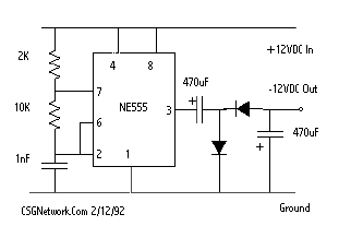
You could make a simple circuit to generate a slightly more powerful -12 V line:

enter image description here

Source.

Note that this negative rail isn't regulated and the voltage will drop when loaded.

Depending on your circuit, this could suffice, the opamps might have enough supply rejection.

If you want a "better" -12 V I would simply use an isolated DCDC converter and then connect its output such that you get a -12 V.

For example use an isolated DCDC converter like this.

There is a 5 V in to 12 V out isolated output model. Then you do need to add a voltage regulator to make +5 V from your +12 V as the DCDC converter is a boost converter, it need to start with less than 12 V.

This solution is not that efficient (some power is lost) but since your power consumption is low that should not be a serious issue.

\$\endgroup\$
5
  • 3
    \$\begingroup\$ Or just use one of these which all have a 12V input and a 12V output, and are isolated. Some of them even take an unregulated 12V input and output regulated ±12V! \$\endgroup\$
    – Hearth
    Commented May 6, 2019 at 14:07
  • \$\begingroup\$ @Hearth I was looking for something like that but could not find them. Thanks. \$\endgroup\$ Commented May 6, 2019 at 14:08
  • 2
    \$\begingroup\$ The trick is to look for things with a minimum of 10.8V and a maximum of 13.2V input; 12V±10%. Digikey doesn't let you search by nominal input, just by input range, which is usually more useful but in cases like this can be unfortunately misleading. \$\endgroup\$
    – Hearth
    Commented May 6, 2019 at 14:21
  • \$\begingroup\$ @Hearth, it was a very good tip. I found this model : PDM1-S12-D12-S ( digikey.com/product-detail/en/cui-inc/PDM1-S12-D12-S/… ) And, taking a look at it's datasheet I saw a EMC recommended circuit. It seems to be very simple, would you have some advice about layout and project using this kind of IC ? \$\endgroup\$
    – Daniel
    Commented May 6, 2019 at 15:06
  • 1
    \$\begingroup\$ @Daniel That PDM1-S12-D12-S is not an IC but a module, just follow the guidelines on the datasheet, adding some decoupling capacitors is always a good idea (like 10 uF + 100 nF in parallel). The idea behind such modules is that they're "foolproof" and easy to use. \$\endgroup\$ Commented May 6, 2019 at 16:25

Your Answer

By clicking “Post Your Answer”, you agree to our terms of service and acknowledge you have read our privacy policy.

Not the answer you're looking for? Browse other questions tagged or ask your own question.