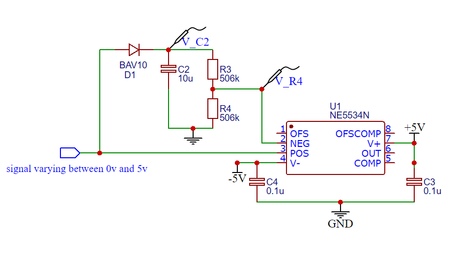
The capacitor C2 keeps the value of a slow varying signal for some time. The capacitor discharges through the two resistors R3 and R4 with a time constant of \$\tau = RC = 10\mu F \times 1M\Omega = 10s\$. The voltage across resistor R4 should be half of the voltage across the capacitor. This works as expected when the op amp (NE5534N) isn't connected to the circuit.
When V_R4 is used as reference to the inverting input of the op amp the voltage changes to about 80% of the voltage across the capacitor C2. I have not been able to find a solution to this. Am I missing something here?

