1
\$\begingroup\$

Circuit Diagram

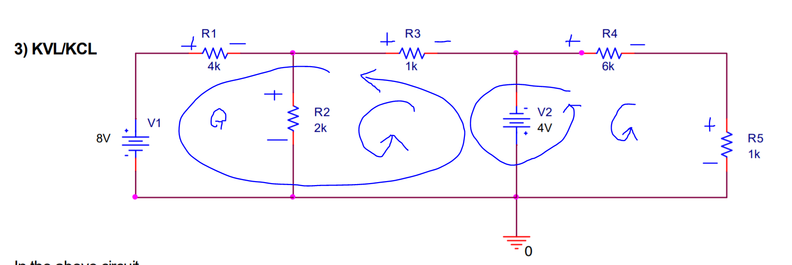
Follow the link to the circuit that I need to solve for all the resistor voltage drops.

I have to make 5 linearly independent equations in order to solve for all 5 unknown voltages.

Using the loops as drawn in the image following the link I get the equations:

1. iR1*4000 + iR2*2000 = 8
2. -iR2*2000 + iR3*1000 = 4
3. iR4*6000 + iR5*1000 = -4
4. iR1*4000 + iR3*1000 = 12
5. -iR2*2000 + iR3*1000 + iR4*6000 - iR5*1000 = 0

And the Matrix:

4000  2000     0     0     0     8

   0 -2000  1000     0     0     4

   0     0     0  6000  1000    -4

4000     0  1000     0     0    12

   0 -2000  1000  6000 -1000     0

When I row reduce this matrix, I get a row of all zeros which indicates that there isn't one unique solution to this matrix. I cant figure out what I am doing wrong as this is impossible. I could probably use different loops but I still need to understand why this configuration does not work. I have the understanding that all of my equations are linearly independent.

Note: There are better ways to solve it but the Question asks to solve it with exactly a 5 x 6 Matrix.

\$\endgroup\$
4
  • \$\begingroup\$ Why more than three loops? Are you just creating more because you are providing all permutations of loops you can see? \$\endgroup\$
    – jonk
    Commented May 20, 2019 at 22:49
  • \$\begingroup\$ @jonk No I have to because the question says to do so. Otherwise I wouldn't need to post here. \$\endgroup\$
    – mk3009hppw
    Commented May 20, 2019 at 22:54
  • \$\begingroup\$ There are only 2 unknown voltages: that across R2 and that across R5. V1 and V2 define the voltages at the other 2 nodes. \$\endgroup\$
    – Barry
    Commented May 20, 2019 at 23:14
  • \$\begingroup\$ @mk3009hppw Ah. I see. I think you are supposed to use three KVL equations and two KCL equations. Is that barred? (Because it looks like that's the only way to arrange it given the 5x6 requirement.) \$\endgroup\$
    – jonk
    Commented May 21, 2019 at 1:09

1 Answer 1

-1
\$\begingroup\$

In the following schematic, \$I_1\$, \$I_2\$, and \$I_3\$ are the interior loops, which I consider to be walked "clockwise" starting always at their lower left corner. Those are set up with KVL. There is also \$V_\text{A}\$ and \$V_\text{B}\$. Those are set up with KCL. This would make for 5 equations and 5 unknowns:

schematic

simulate this circuit – Schematic created using CircuitLab

So, it's my belief that you were being asked to solve for all three loop currents using KVL and both unknown node voltages using KCL. The equations would be:

$$\begin{align*} 0\:\text{V}+8\:\text{V}-4\:\text{k}\Omega\,\cdot\,I_1-2\:\text{k}\Omega\,\cdot\left(I_1-I_2\right)&= 0\:\text{V}\\\\ 0\:\text{V}-2\:\text{k}\Omega\,\cdot\left(I_2-I_1\right)-1\:\text{k}\Omega\,\cdot\,I_2+4\:\text{V}&=0\:\text{V}\\\\ 0\:\text{V}-4\:\text{V}-6\:\text{k}\Omega\,\cdot\,I_3-1\:\text{k}\Omega\,\cdot\,I_3&=0\:\text{V}\\\\ \frac{V_\text{A}}{4\:\text{k}\Omega}+\frac{V_\text{A}}{2\:\text{k}\Omega}+\frac{V_\text{A}}{1\:\text{k}\Omega}&=\frac{8\:\text{V}}{4\:\text{k}\Omega}+\frac{0\:\text{V}}{2\:\text{k}\Omega}+\frac{-4\:\text{V}}{1\:\text{k}\Omega}\\\\ \frac{V_\text{B}}{6\:\text{k}\Omega}+\frac{V_\text{B}}{1\:\text{k}\Omega}&=\frac{-4\:\text{V}}{6\:\text{k}\Omega}+\frac{0\:\text{V}}{1\:\text{k}\Omega}\\\\ \end{align*}$$

I'll let you sort out the matrix from the above statements. It will have a solution.

The results will be \$I_1= 2\frac27\:\text{mA}\$, \$I_2= 2\frac67\:\text{mA}\$, \$I_3= -\frac47\:\text{mA}\$, \$V_\text{A}=-1\frac17\:\text{V}\$, and \$V_\text{B}=-\frac47\:\text{V}\$.

From that you can, of course, completely work out all necessary voltage drops across the resistors, too.

\$\endgroup\$

Your Answer

By clicking “Post Your Answer”, you agree to our terms of service and acknowledge you have read our privacy policy.

Not the answer you're looking for? Browse other questions tagged or ask your own question.