1
\$\begingroup\$

enter image description here

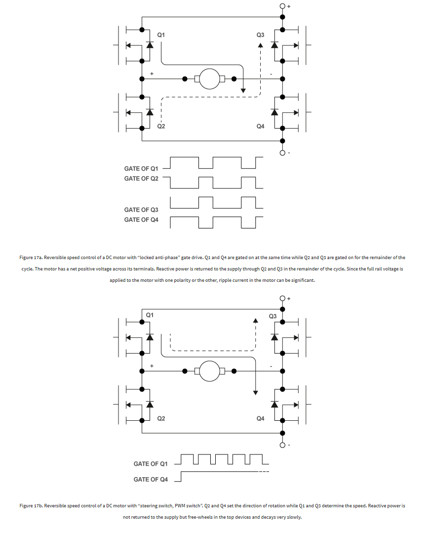
Hello. I want to inquire the method that describes when, one side is ON/OFF(fig.17.b), and the other goes with PWM. The point is, wheather both of mosfets (high & low side) will be on/off and some extra mosfet on the power supply ground will be added, that will respond for PWM at this time now, will it keep the advantage when the power do not flow back to psu?

I guess not, but such a point)

Thank you.

In Figure 17a the two transistors in each half-bridge are both driven in anti-phase with a PWM square wave. Q1 and Q4 are gated on at the same time while Q2 and Q3 are gated on for the remainder of the cycle. At 50% duty cycle the average voltage across the motor is zero. As the duty cycle increases in one direction or the other the motor sees an average voltage at its terminals that can be positive or negative, depending on the duty cycle. Two switches are always gated on and apply a defined voltage to the motor, as determined by the control board. Change in direction is as natural as a change in duty cycle. Current can flow in both direction and the motor can motor or regenerate. Notice that, during the first part of the cycle (transistor current), power is delivered to the motor. During the remainder of the cycle power is returned to the supply. The control method shown in Figure 17b uses the lower switches to determine the direction of the motor (Q4 in the example), while the upper switches are PWM-modulated to regulate the speed. This method is similar to the one represented in Figure 16. Notice that only two switches are gate-controlled on or off, while the other two have zero volts applied to the gate. In some instances the direction of the current establishes the voltage applied to the motor and it may be different from what is commanded by the control board. A change of direction requires a change-over from one transistor pair to the other, a common source of control headaches. The first method gives better servo performance while the second method gives much lower ripple current in the motor for the same operating frequency. With this modulation method power is not returned to the supply. Current free-wheels in the top devices and decays, as determined by the losses.

\$\endgroup\$
3
  • 1
    \$\begingroup\$ I'm really not sure what you are asking or talking about. \$\endgroup\$
    – Andy aka
    Commented Jun 6, 2019 at 7:39
  • \$\begingroup\$ Andy aka, sorry but, if you will be more attentive, you could understand. \$\endgroup\$
    – Sieben
    Commented Jun 10, 2019 at 7:58
  • \$\begingroup\$ Please yourself. \$\endgroup\$
    – Andy aka
    Commented Jun 10, 2019 at 8:14

1 Answer 1

1
\$\begingroup\$

A full H bridge using Nch FETs is often done with discrete FETs or dual half-bridges.

Normally with positive supplies, and Nch Enhancement FETS preferred, the low side FET gate voltage uses the single supply voltage with PWM. WHile the High side controls direction with a diode-cap charge pump (from PWM pulsed voltage) to create a boost voltage above Vdd for the high side Vgs.

The 1st method is only used for special low power motors that can handle the ripple current and power dissipation.

The 2nd method uses dynamic PWM braking to shunt the EMF current to slow down to stop then applies direction change to accelerate in reverse.

Deadtime in micro-seconds depends on the motor L/R time constants.

You can start learning with a half-bridge IC Theory of Operation in many places. e.g. here

\$\endgroup\$
8
  • \$\begingroup\$ Thank you. Took the description from here) irf.com/electronics/topology-fundamentals Noted also the reverse of sides described there, what responds for what. ) \$\endgroup\$
    – Sieben
    Commented Jun 6, 2019 at 7:40
  • \$\begingroup\$ i.ibb.co/0ccvjhw/post-183731-0-07175400-1454966028-thumb-1.png So, provide the picture of the subject. SunnyskyguyEE75, will that stop ripple currents to go back with this method too? Big thanks. Please don't pay much attention to the H-bridge config itself, just the configuration on the whole. I already build one with relay instead of the mosfets. All is working. But really will be good to stay clear of the matter. ) \$\endgroup\$
    – Sieben
    Commented Jun 10, 2019 at 8:05
  • 1
    \$\begingroup\$ Inductors integrate pulse voltage into triangle currents (ripple) which will accelerate or de-accelerate motor depending on duty cycle. When one side opens, there must be a flyback (reverse) diode to shunt the voltage \$\endgroup\$
    – D.A.S.
    Commented Jun 10, 2019 at 14:15
  • \$\begingroup\$ Sunnyskyguy EE75, I need help. Based on this connections, i.sstatic.net/qaop0.png Made up this raw diodes placements. i.ibb.co/5hgyBZ6/Screen-Shot01815.jpg Will that be enough not to burn the mosfets? And if not use the zeners in motor clamps, or cross the mosfet. I hope the locations are correct too. The diodes are F30U60DN. The motor itself, can give a bit higher the 30A Stall current there, with 12v on it etc. Almost constant stall current condition, and rapid direction changes in the application it is used. \$\endgroup\$
    – Sieben
    Commented Jun 20, 2019 at 9:35
  • \$\begingroup\$ Saw yours solution you made, of course too. But still have that question. electronics.stackexchange.com/a/318153/222816 \$\endgroup\$
    – Sieben
    Commented Jun 20, 2019 at 9:36

Your Answer

By clicking “Post Your Answer”, you agree to our terms of service and acknowledge you have read our privacy policy.

Not the answer you're looking for? Browse other questions tagged or ask your own question.