1
\$\begingroup\$

I have an 2-port HDMI switch that swaps inputs using a 6-pin DPDT latching push button. I want to modify it to be controlled by a GPIO pin on my Pi rather than having to push the button.

One way that was suggested to me was desoldering the button and replacing it with two H-bridges driven by 4 GPIO pins.

Alternatively, I'm wondering if I could keep the button in place, and instead replace the button "plunger" with an NPN driven by a single GPIO. Would that be feasible?

\$\endgroup\$
1
  • 1
    \$\begingroup\$ You might be able to find a 3.3v DPDT relay that matches the pin layout, you could then drive that with a PN2222A, a resistor, and a diode to drive it from a single pin. \$\endgroup\$
    – Ron Beyer
    Commented Jun 27, 2019 at 3:29

2 Answers 2

1
\$\begingroup\$

Modify HDMI DPDT push button with an NPN to control with GPIO pin?

It will be quite easy to modify, though there are two distinct circuits you need to drive separately. You will need to remove the DPDT switch to get correct remote operation.

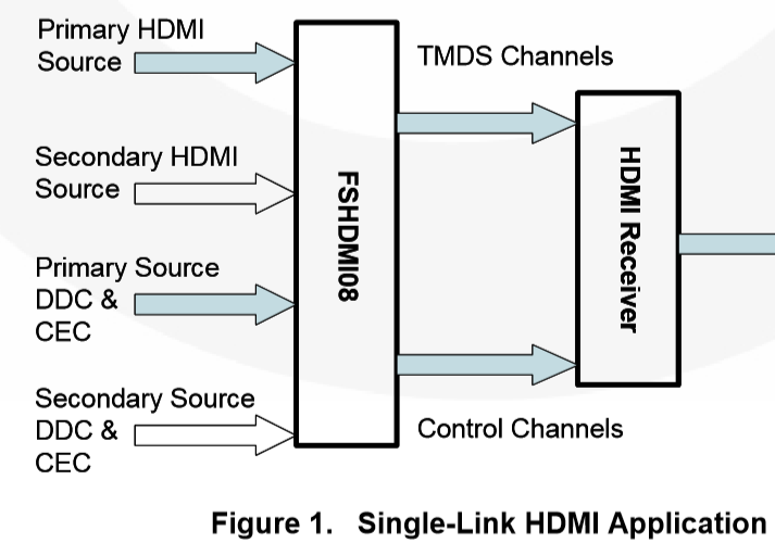
  1. HDMI switches (with manual pushbutton selection) all use one of various HDMI multiplexers to change the TMDS/Clock and DDC/CEC signals from one source to the other. This multiplexer is usually controlled by a logic signal which could be directly driven by external logic.

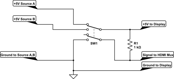
  2. There may be a simple SPDT switch (one half of your physical pushbutton switch) which switches over the +5V supply from one source to the other.

A typical chip used for the data switch may be like this FSHDMIO8
enter image description here

The most likley configuration inside you switch box would be like this:
schematic

simulate this circuit – Schematic created using CircuitLab

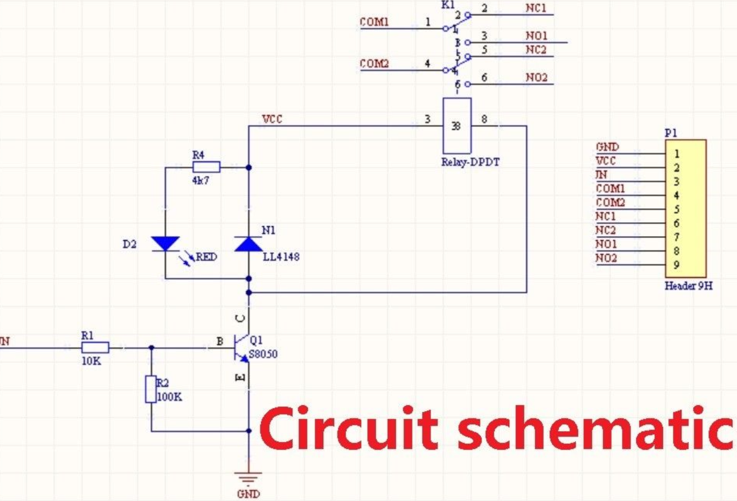
If you remove the DPDT switch you should be able to wire in a relay module made for Arduino use without too many problems. An example of what you could source is here and it's schematic shown below. Search for "DC 5V DPDT Relay Module Board for Arduino" and you'll find several options.
enter image description here

This particular module drives the relay with an NPN transistor and will work (the IN signal) for both 3.3V and 5V MCUs, however the itself relay requires 5V for operation. For example this would work if your MCU were a Raspberry Pi, where the I/O signals are 3.3V but there is 5V available to power the relay.

\$\endgroup\$
2
  • \$\begingroup\$ Other than using only 1 GPIO pin, is there any benefit to using a relay over an H-bridge? Specifically, I'm looking at a quad half H-bridge like the one here which should be able to drive both circuits. Looks slightly cheaper and comes in a smaller package, and wouldn't need an extra NPN. \$\endgroup\$
    – Donald
    Commented Jun 28, 2019 at 3:40
  • \$\begingroup\$ @Donald An H-bridge to do what? ….turn on a relay? ….completely unnecessary to drive a relay, and simply won't work to drive a logic signal. \$\endgroup\$ Commented Jun 28, 2019 at 5:08
2
\$\begingroup\$

Not really feasible. Especially with the lack of design requirements, schematics and what you have tried so far. With that said I suggest that you desolder the DPDT switch and substitute the contact connections of a small DPDT relay. Use your GPIO to drive an NPN transistor that in turn drives the relay coil.

\$\endgroup\$
1
  • \$\begingroup\$ Yep, makes sense. I ended up opening up the button out of curiosity and couldn't imagine anything that would work. Not easy to find schematics, or even identify the manufacturer for that matter. \$\endgroup\$
    – Donald
    Commented Jun 28, 2019 at 3:46

Your Answer

By clicking “Post Your Answer”, you agree to our terms of service and acknowledge you have read our privacy policy.

Not the answer you're looking for? Browse other questions tagged or ask your own question.