No, you do NOT requires a pulldown resistor for the gates. This is already built into the driver and the driver when powered on will immediately have a defined state.
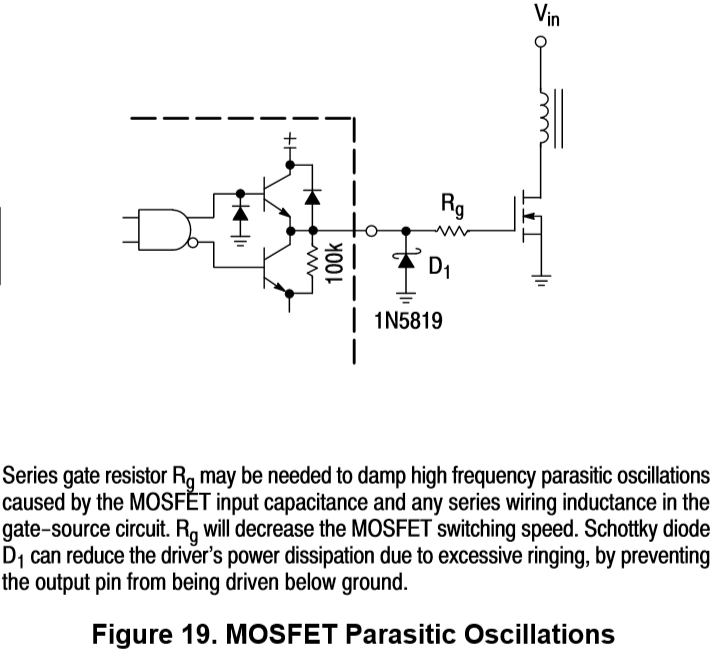
You MAY require a series resistor since the the driver is rated for only 1.5A maximum. The series resistor is used to limit maximum current and reduce parasitic ringing which may increase dissipation in the output FETs.
As shown in the datasheet:

As mentioned in another answer you could put a diode across the motor to control back EMF instead of the capacitor, but neither of these are a good solution.
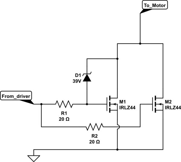
The best way to get rid of the stored energy as fast as possible is to use a Zener across your drive devices. If you do this you will definitively require a series resistor from the driver to the gates since the Zener will hold the drive FETs on to dissipate the back EMF..
Update: One of the comments exposed (@DKNguyen) exposed the potential for gate oscillations between the paralleled FETs, and linked to this paper.
From this it would appear prudent to include a separate series resistor for each FET gate to reduce the Q of any parasitic elements.
Now however you definately will only use one of the FETs (the one with the Zener Drain-Gate) to limit the back EMF, even if the are well matched.

simulate this circuit – Schematic created using CircuitLab


