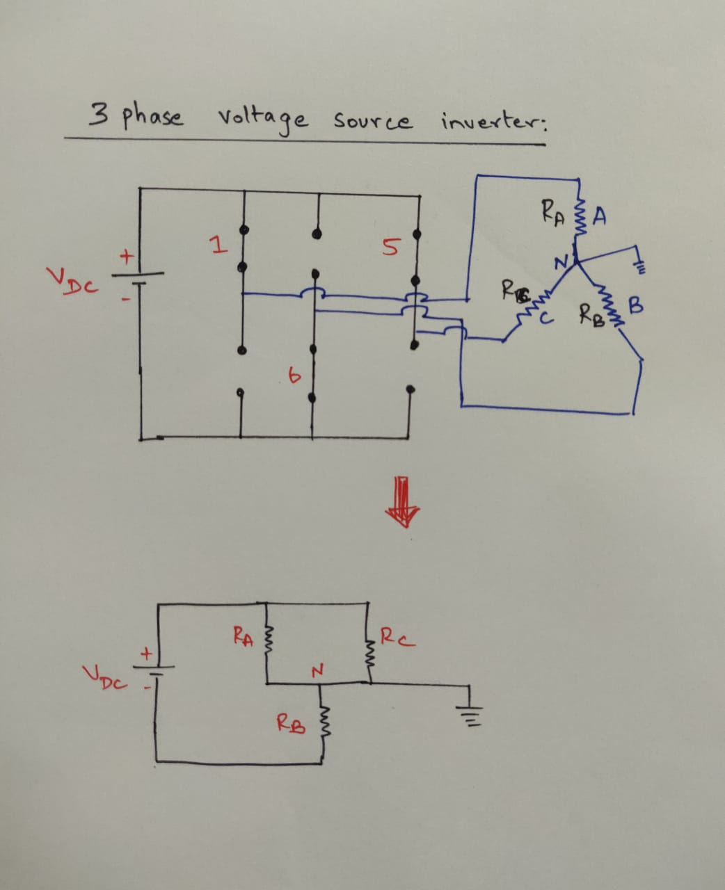
I'm having trouble understanding how current flows in loops in this drawing. Does current flow from the battery to the 3 windings and then back to the negative terminal of the DC source?
Yes, your lower diagram is correct but 'N' suggests that this point is neutral (meaning that it is has no significant voltage on it) and this may not be true, depending on whether the battery or inverter is grounded or not.
Or does the current flow to the neutral that is grounded?
No. There is no other connection to earth or "neutral" in your circuit so there is closed circuit for the current to flow.
What exactly is the neutral point in this case? Is it just a reference point to measure voltage or does it have an extended wire that is connected somewhere else in the circuit?
No point other than being the star or wye point of the load.
If the neutral point is just a reference point, then the three phase circuit gets of any 1 switching state gets reduced to an equivalent circuit of resistors in series and parallel.
Correct.
For example, the equivalent circuit drawn when switches 1,5,6 are on doesn't seem to be like an AC generating circuit. Seems just like two resistors in parallel with the combination in series to a third resistance. So how is this combination of resistors able to generate a sinusoidal waveform?
It's not. I explained this in my answer to your question Meaning of firing angle in the context of a DC input supply.

Figure 1. The simple inverter produces square waves - not sines.
In your system the star point will jump up and down between 1/3 and 2/3 of the DC supply, depending on the switching sequence as discussed in the previous question.
To generate a sinewave PWM (pulse-width modulation) is carried used and this can, for many load types, provide an adequate approximation to a sinewave, particularly with filtering. Have a look at variable frequency drive (VFD) operation which uses similar technology.
====
Response to comments:
Is there any reason why the neutral is the star point?
Because that's where you have connected your circuit to ground. Earthing any point in a circuit "neutralises" it. There will be no voltage on that node with respect to earth. It's not a great idea as with this circuit the battery terminal voltages will be jumping up and down with respect to ground.
And as Rb is between the neutral and negative terminal of the battery in this case, is this why the voltage Vb is negative?
It's only negative when switch 6 is closed. Otherwise it will be positive.
Moreover how can I visualize a negative value of current Ib flowing through Rb? Would this be an AC or DC current?
'b' will be switched alternately between battery + and - so the current through it will alternate so it will be AC.


