11
\$\begingroup\$

There are a variety of integrated circuits that specify that their input voltage can span a fairly wide (absolute maximum) range, e.g. -0.3V to 6.0V (ref, pdf page 4), and then have a "Input Voltage at any pin" constrain that depends on the input voltage, e.g. -0.3V to VDD + 0.3V.

That, in effect, makes the chip not be I/O tolerant to voltages that exceed the input voltage by more than 0.3V but are within the absolute maximum specs of what the input voltage allow, and forces me to apply some kind of external level shifting circuit to those inputs.

So what is the practical reason for this kind of limitation in the specifications for integrated circuit I/O pins?

\$\endgroup\$
3
  • 3
    \$\begingroup\$ if the input protection diodes are standard PN junctions, and have "large areas" with many contacts into anode and into cathode regions, then I suggest you plan on: 10mA at 0.7v, 1mA at 0.64v, 0.1mA at 0.58v, 0.01mA at 0.52v, 0.001ma (1uA) at 0.46v, 0.1uA at 0.40v, 0.001uA at 0.34 volt. Is ONE NANO_AMP low enough, to not cause errors? { note; these numbers can easily be off by 10:1 in current } \$\endgroup\$ Commented Sep 18, 2019 at 15:19
  • 1
    \$\begingroup\$ The "Absolute Maximum" ratings are just that - you don't want to operate the part near those ratings. There is usually a note below the "Absolute Maximum" ratings table that says something like "Operation at or beyond these ratings may damage the part". Beginners often fail to read that note. \$\endgroup\$ Commented Sep 18, 2019 at 15:38
  • 3
    \$\begingroup\$ "and forces me to apply some kind of external level shifting circuit to those inputs". That tends to suggest you're interfacing to external equipment, at which point an interfacing circuit to protect your micro should be part of your design. Conversely, if you're level-shifting to talk to another chip on the board, then you've probably chosen the wrong chip to use. \$\endgroup\$
    – Graham
    Commented Sep 19, 2019 at 9:59

4 Answers 4

23
\$\begingroup\$

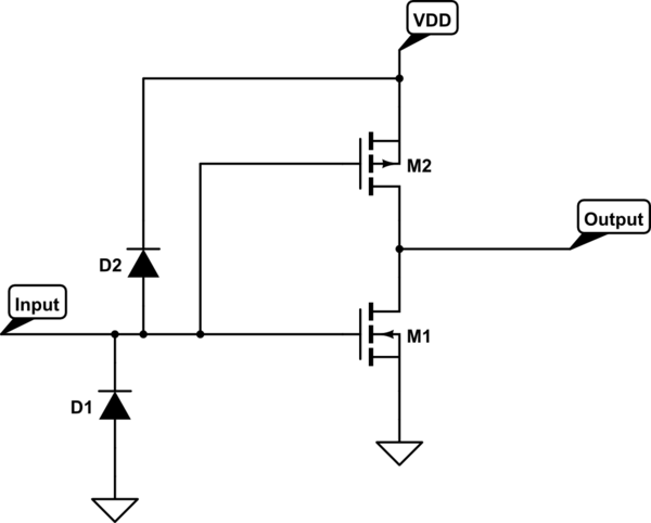
Most likely there is an ESD protection diode connected between the input pin and the VDD net on the chip, in such a way that it is normally reverse biased (A schematic showing the configuration is given in Peter Smith's answer). The idea is that when there is a positive ESD event, current will flow into the lower-impedance VDD net where it will do less damage than if it's all dumped on the one poor CMOS gate that's attached to the input pin.

Because the limit is VDD + 0.3 V it's likely in your device the diode is a Schottky type instead of a PN junction. With a PN junction, you'll usually see a limit of VDD + 0.6 V or so.

If you were to apply an input voltage above VDD (by more than 0.3 or 0.4 V) to this device, you'd forward bias this diode, and draw a high current from your source. This might damage your source or, if the source can supply enough current, heat up the chip to the point of damage.

If you use a resistor to limit the current into the input pin under these conditions, you might find the circuit works fine. Or, particularly if the chip is a very low power one, you might find the whole chip (and maybe other things connected to the same VDD) are powered up through the input pin, which often leads to unintended behavior.

\$\endgroup\$
2
  • 1
    \$\begingroup\$ I think this is probably the best answer, and I appreciate that it recommends it offers the possibility that current limiting resistors might mitigate the ESD protection diodes failing in a sustained condition. It would benefit from a representative schematic, similar to what @PeterSmith provided. \$\endgroup\$
    – vicatcu
    Commented Sep 18, 2019 at 15:20
  • \$\begingroup\$ @vicatcu, I have edited to address your concern. \$\endgroup\$
    – The Photon
    Commented Sep 18, 2019 at 16:08
18
\$\begingroup\$

This is due to the input protection diodes.

A typical input looks like this (CMOS inverter shown):

schematic

simulate this circuit – Schematic created using CircuitLab

The diodes in newer parts are schottky devices. These diodes are for short, low energy transient events and cannot handle much current (a few mA generally).

\$\endgroup\$
1
  • \$\begingroup\$ They are for short, low energy transient events but that doesn't keep "clever" circuit designers to exploit them as regular diodes. For example, interfacing 12V signal with a 3.3V part by simply adding a large valued resistor, and letting the protection diodes handle the extra voltage. \$\endgroup\$
    – hjf
    Commented Sep 19, 2019 at 19:05
11
\$\begingroup\$

The 0.3V drop comes from the Schottky clamping diodes used to protect the pins of the chip. These diodes typically connect between each pin and the two power rails. If they are forward biased by more than 0.3V, arbitrarily large currents can flow.

The diodes are designed to absorb transient currents produced by ESD, which represent limited amounts of energy that they can handle, protecting the sensitive MOSFET gates from overvoltage. But if you drive them with a low-impedance source, you'll quickly dump more energy into them than they can handle.

\$\endgroup\$
3
  • \$\begingroup\$ "Arbitrarily large currents" sound like the might be pretty detrimental to the chip. In that case how can those be said to be offering protection? Only in a very limited band of 0.3V around the range GND to VDD? Also your answer might be improved, for less experienced readers, by including a little representative schematic of what the pin logically might look like at the perimeter of the chip. \$\endgroup\$
    – vicatcu
    Commented Sep 18, 2019 at 15:14
  • 2
    \$\begingroup\$ @vicatcu The "arbitrarily large currents" are if (for example) you were to connect a 3.3V powered device's input to a 5V or 12V power supply or other low-impedance source. The diodes are intended to protect against limited-energy ESD transients, not to protect against any and all arbitrary input signals that might be connected. \$\endgroup\$ Commented Sep 19, 2019 at 2:34
  • \$\begingroup\$ right on, I can dig it \$\endgroup\$
    – vicatcu
    Commented Sep 19, 2019 at 2:52
6
\$\begingroup\$

Actually, the Schottky clamping diodes and the VDD + 0.3V are both present for the same root cause and that is SCR Latch-up. The design of all CMOS ICs actually creates a pair of BJT transistors intrinsically. It simply results from out the p-type and n-type silicon substrates are laid out. This picture from VLSI Universe shows it well:

https://1.bp.blogspot.com/-yUiobLvxMrg/UTvnjjzaXZI/AAAAAAAAABc/lRFG5-yqD3E/s1600/latchup.JPGSCR Latch-up
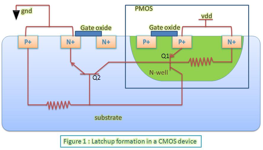
You get two intrinsic BJT transistors, Q2, and NPN, and Q1, a PNP. Note, they share the one N-well and one P-well, but this particular arrangement forms something called a Silicon Controlled Rectifier (SCR). This is not desired in anyways, but an unfortunate side-effect of this arragement. It is not a problem if certain rules are followed.

A typical SCR has three terminals, Anode, Cathode, and Gate. In general, it is forward-biased for some device that must be controlled with a positive voltage at the Anode with respect to the Cathode, however, the SCR will block any current unless the Gate is activated. To activate the Gate, it must rise across a threshold which, in this design, will be the Anode voltage. One the latch is activated, it will stay on even if the Gate drops. It will stay on until the Anode voltage drop to near zero current. For the CMOS IC, the Cathode is akin to the chips GND, the Anode is the VDD rail, and the Gates are the I/O Pins. This is the crux, if any I/O pin rises much above VDD, it will enable the latch and create a short between VDD and GND causing a very large amount of current and that current will keep the latch going burning up the IC.

To help protect against this for small transient spikes, Shottky diodes are added to the I/O lines to clamp the input to GND - 0.3V and VDD + 0.3V inside the safe zone. These diodes can only take a small amount of current and external clamping can still be required for more rugged designed.

For more info, EEVblog did a nice tutorial on this: EEVblog #16 - CMOS SCR Latchup Tutorial

\$\endgroup\$
2
  • \$\begingroup\$ I've also encountered a part (I think it was 74HCxx) which behaved as though each pair of inputs had a PNP transistor between them, with the base tied to VDD. One input happened to be weakly pulled down while the other was pulled above VDD by about 100uA. A small enough current that chip damage would have been a non-issue, but much of that 100uA flowed out onto the adjacent input. \$\endgroup\$
    – supercat
    Commented Sep 20, 2019 at 19:58
  • \$\begingroup\$ oh interesting maybe this is really the answer... \$\endgroup\$
    – vicatcu
    Commented Sep 21, 2019 at 14:15

Your Answer

By clicking “Post Your Answer”, you agree to our terms of service and acknowledge you have read our privacy policy.

Not the answer you're looking for? Browse other questions tagged or ask your own question.