1
\$\begingroup\$

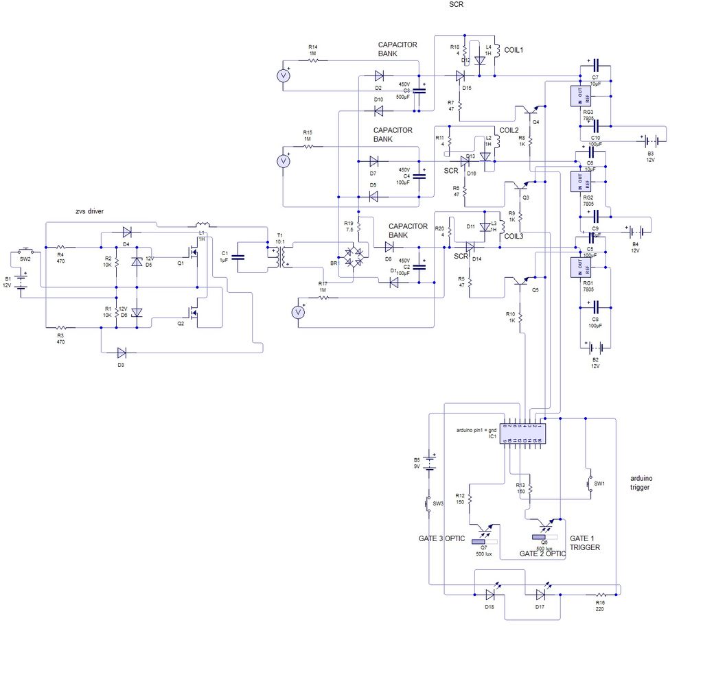
I'm trying to charge three capacitors by using my country's net voltage of 230V (60Hz) AC. The net voltage is connected to a diode bridge, which thereby results in approximately 325V DC. Each capacitor can hold 2200uF with up to 450V. I wanted a charging time of approximately 60 seconds, so I should put it in series with a 5.6kOhm resistance. Each capacitor should be connected to a coil, such as seen in circuit one down below.

circuit 1

I've figured this firing circuit out myself, however, I'm still confused about the charging circuit for the projectile accelerator. See this image below:

circuit 2

In this image, we can see the firing circuit, the diode bridge part of the charging circuit and the 'transformer part' of the charging circuit. I'm still a little confused about the diode bridge part.
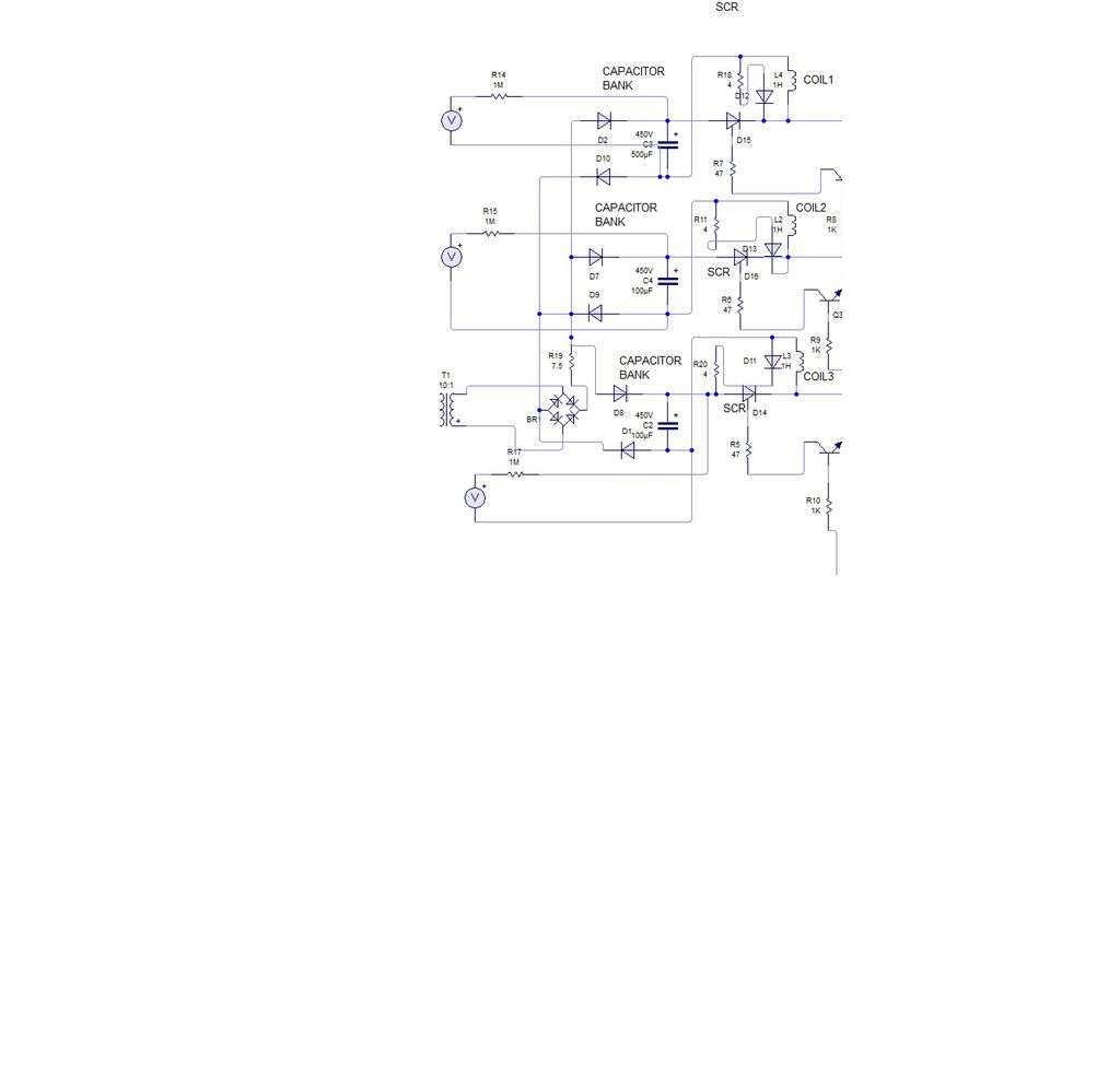
circuit 3Will the current of the diode bridge be split over each of the capacitors and how about the amperage? Should I put the mentioned resistance in series of each capacitor, or just in series of the positive output of the diode bridge. Are the diodes before and after each capacitor really necessary? How come that when allowing the first capacitor to discharge over the first coil, the other capacitors will not discharge? As this should not happen, because the other two capacitors are necessary for the second and final coil.

And of course, last but not least: Is the way shown in circuit 2 the right and/or best way to do what I'm trying to achieve?

Thanks in advance and my apologies for the perhaps incorrect usage of specific physics terms, as I'm used to using those of my own language of origin. If anything is still unclear feel free to ask me for clarification

\$\endgroup\$
1
  • \$\begingroup\$ Can you clarify where the AC is connected? \$\endgroup\$ Commented Oct 26, 2019 at 22:06

1 Answer 1

0
\$\begingroup\$

Will the current of the diode bridge be split over each of the capacitors and how about the amperage?

With the series resistor where it is, all the current will flow to the capacitor with the lowest charge. The other capacitors will reverse bias their diodes until the lowest capacitor charges up to a similar voltage. Once capacitors are at similar voltage, then the current will start to share between them to maintain that similar voltage.

Should I put the mentioned resistance in series of each capacitor, or just in series of the positive output of the diode bridge.

If you move the resistance to each branch, then the capacitors can charge at the same time. In that case you can think of it as a DC voltage source connected to 3 resistor-capacitors in parallel. The current in each capacitor will be inversely proportional to the charge in each capacitor. In other words, the capacitor with the least charge (and therefore the lowest terminal voltage) will receive the greatest proportion of the current, because the voltage across the series resistor will be greatest.

Either way, the capacitors will eventually charge, so it's probably up to you.

Are the diodes before and after each capacitor really necessary?

Only if you want to prevent one capacitor charging another. Assumedly this is desirable, since it means you can discharge one capacitor and still have charge remaining on the others.

Nonetheless, you only need one diode per capacitor to do this. I can't see any reason why you'd have one connected to each terminal, but I might have missed something.

How come that when allowing the first capacitor to discharge over the first coil, the other capacitors will not discharge? As this should not happen, because the other two capacitors are necessary for the second and final coil.

See previous answer - the diodes prevent charge leaving a higher voltage capacitor to charge a lower voltage capacitor. The diodes act as a one-way valve - the capacitors can be charged by the left-hand side of the circuit, but they cannot provide charge back the other way.

And of course, last but not least: Is the way shown in circuit 2 the right and/or best way to do what I'm trying to achieve?

There's no "right" way, and "best" depends on a lot of factors, many of which are probably not known to us. I highly recommend simulating it first, even in multiple simulations that focus on one aspect at a time. Fundamentally, if your goal is to charge 3 capacitors from an AC mains supply, and you're happy to have roughly 325V DC on your capacitors, then this is probably good enough. Just be very, very careful that everything is rated appropriately before switching it on - mains voltage can turn capacitors and rectifiers into hot, exploding messes awfully quickly if something goes wrong. Make sure you get someone else to check over your work before applying power.

\$\endgroup\$

Your Answer

By clicking “Post Your Answer”, you agree to our terms of service and acknowledge you have read our privacy policy.