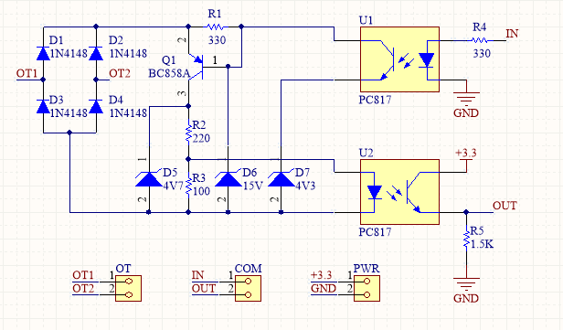
Yes, this circuit allows an OpenTherm thermostat to receive current signals and to output voltage signals, all on the same line, in line with the OpenTherm specification. It does not provide remotely the (3V3) power supply.
The first reply (from @bigjim) is correct for the transmission part: a high voltage on the IN pin will saturate the transistor in U1, so the 4V3 zener kind of replaces the 15V, so the voltage on OT1-OT2 will change from 15V+3x0.7V (17V) to 4V3+3x0.7V (6.4V).
For the reception part, it's a bit different: when the boiler wants to send a 0 (idle state), it keeps the current to 7mA. Assume for one moment Q1 isn't there, then the voltage on R1 would be 330*0.007 = 2V. So we can deduct that Q1 is always ON, and voltage on R1 is always 0.7V, hence current in R1 is about 2mA. Current in zeners is also 2mA (+ neglictible base current), so no risk of killing them. The other 5mA flow through R2 and R3, so V on R3 is only 500mV, and OUT is low. It doesn't vary with OT voltage, the difference only affects Vce of Q1 (either 3.2V or 14V).
When current moves to about 20mA, there is still the same current in R1 and the zeners, so there is now 18mA through the transistor, which would bring voltage to 5.7V on the collector of Q1. That doesn't happen because of the Zener D5, that limits that voltage to 4.7V, hence the current in R2 and R3 to 14mA max. But now VR3 would be 1.4V, so U2 lights up, and OUT is positive.
Note that I used Vbe and Vdiode = 0.7V, this can vary, but won't affect the explanation.
Regarding the role of D5 and D6, they are quite different : D5 allows the boiler to see that there is a thermostat (otherwise the voltage on OT could go higher/out of specs). D6 allows to keep the current in R2 and Q2 in a safe range (Iot could be as high as 23mA, hence maybe more than 20mA in the LED in Q2, depending on its voltage drop)

