0
\$\begingroup\$

I have 102 White LEDs in total and I want to drive them from the 110V rectified Mains in 34S 3P configuration.
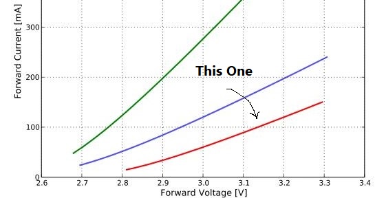
Here's the graph about the LEDs (Red Line).

enter image description here

I want to pass only about 50mA through them so that they remain cool because they would be mounted on a flexible material with minimal heat-sinking. They would require output power from IC -- One Led = 3V x 0.05A = 0.15W
102 Leds 0.15W x 102 = 15.3W
Now I have chosen an appropriate mains rated LED driver for these LEDs (Transformer Less non isolated type, low flicker, high PF, Low EMI etc). And while I was designing the circuit and reading the power dissipation of the IC it showed power dissipation from 2W to 3.5W from best to worst case scenario.

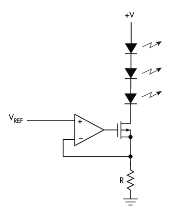
That's when I thought why not design a linear constant current source for mains voltage to drive the LEDs because when I thought about it it did made sense.
Best case scenario: Led driven at 3V @ 50mA each, 34 Leds in series = 102V
3 parallel strings total current = 200mA
Power Dissipation = 110V - 102V = 8V and 8V x 0.2A = 1.6 Watts.
Worst Case: Mains Voltage reaches 130V and thus
Power Dissipation = 130V - 102V = 28V and 28V x 0.2 = 5.6 Watts.

So I personally think that in this case the Linear Approach offers a lot of advantages like very low EMI, low flicker and can be made compact as well because space is limited. Something like this:
https://www.electronicdesign.com/analog/illuminating-look-led-driving

Thus I have two questions:
1. I know the advantages of this approach but I do not know the cons when you compare it to any transformer-less switching IC like the ONSemi FL77944 so any help would be appreciated.

2. I search for this kind of implimantation on the internet but was not able to find anything like this, and it is a fairly simple approach but why are manufacturers avoiding this kind of approach for high count LEDs in Series. Is there something I am missing?

Edit: 1. There is very limited volume to place the PCB like 12 cm3.
2. As @Transistor pointed out I forgot to considered the variation in the AC how that would affect the efficiency.
3. The PCB would be encapsulated and sealed in something like a potting compound.
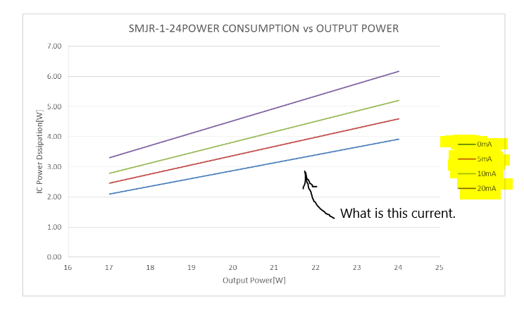
4. The Driver I am considering to use is Seoul Semiconductors Nano driver SMJR-N-1-24 so any info on how to connect those string to this driver would be helpful and as this driver also does not require an isolation transformer then would that meet the commercial requirement?
5. I am now abandoning that idea and would like that off the shelf solution like the Nanodriver because there are a lot of factors involved that I had not considered and would likely mess something up.
6. Also what are those different currents in mA in the graph below. Nano Driver Datasheet

\$\endgroup\$
8
  • 1
    \$\begingroup\$ Your simple approach ignores the fact that your 110 V mains is an alternating voltage which can be anywhere between 0 V and 110√2 = 0 to 155 V peak at nominal voltage. \$\endgroup\$
    – Transistor
    Commented Dec 7, 2019 at 17:07
  • 1
    \$\begingroup\$ @Transistor At the very top of the question's text, the OP writes, "I want to drive them from the 110V rectified Mains." (Emphasis is mine.) The OP may be considering some kind of non-isolated bridge rectifier and capacitor filtering situation, with or without inrush limiting. The only thing, for sure, is that it is supposedly rectified, though. I'm just guessing about the capacitors. \$\endgroup\$
    – jonk
    Commented Dec 7, 2019 at 17:27
  • \$\begingroup\$ This is for simple lighting? Your proposed solution has merit for a more precise application. For simple illumination, a crude series resistor (ballast resistor) is likely sufficient. \$\endgroup\$
    – glen_geek
    Commented Dec 7, 2019 at 18:19
  • \$\begingroup\$ @glen_geek Yeah. That's exactly what I was thinking, seeing the opamp. However, the ballast resistor and the likely variation of LEDs to presenting differing voltages with the same series current in them means some writing about load line analysis for worst case situations. The simple formula, while easy and often "good enough", leaves much to be desired when considering what the worst case might be. I have three or four cheap alternative non-opamp thoughts for the OP to consider. I don't know if I'll write, though. (No LED datasheet provided.) \$\endgroup\$
    – jonk
    Commented Dec 7, 2019 at 18:23
  • 3
    \$\begingroup\$ Have you read the UL White Book regarding appliance safety with high voltages? If this is a commercial product, you'll have to anyway (unless you plan to just slap a fake CE on it and sell it through the Alibaba s**tstream). If it's a hobby project, keeping voltage under 36V means not having to buy funeral attire or deal with a district attorney. Since you plan to use a proper electronic driver anyway, low voltage isn't far out of your way. \$\endgroup\$ Commented Dec 7, 2019 at 18:39

3 Answers 3

4
\$\begingroup\$

Some Initial Thoughts

If your AC mains isn't completely floating (and my experiences are admittedly limited regarding AC mains supplies around the world), then you should consider isolating it with an isolation transformer. And if you are willing to consider it, then you are free to also select whatever secondary voltage that's convenient to both you and their manufacturers. (Everything in the world is "mutual.")

If you want the LEDs to be galvanically connected to your AC mains supply, then you have different responsibilities in terms of enclosures and considering various possible failure modes for those enclosures that might galvanically expose people to the AC mains.

And in all cases, it's a good idea to consider how your arrangements will behave with any single-point failure. There is enough power involved here that some circumstances may generate enough heating at a single point that a fire might result. So, be as comprehensive as possible in your thinking, as you proceed through the project.

Also, long strings of LEDs require higher voltages. Even isolated, if you expose the LEDs themselves to contact, it's possible for someone to bridge across those voltages. A safer direction might be to keep the high-end voltages at a point where most authorities consider it "relatively safe," such as around \$48\:\text{V}\$ or less. (I very much liked the fact that "Harper - Reinstate Monica," in a comment, brought up this voltage issue -- though suggesting still less than I am here. It's important and it's not difficult to do once you've decided to include an isolating transformer in the project.)

If I were considering this project, I'd avoid anything higher than \$48\:\text{V}\$ as the top rail voltage. That's the peak. The allowable ripple would subtract from that. So I might shoot for \$45\:\text{V}\pm 3\:\text{V}\$ as my rail supply.

There is no LED datasheet provided, so I can only suggest that you consider the idea that the variation of voltages on the LEDs, with a given current through them, should be considered to be about \$\sigma\approx 60\:\text{mV}\$ at whatever design current you settle on. There are z-tables where you can go to find out the likelihood of any one chain of N devices to present a given string-voltage, so I won't bother with that. If you want to gamble on \$1\,\sigma\$, that's your call. I'd prefer a \$3\,\sigma\$ assumption. And lacking a datasheet, this means \$\pm 200\:\text{mV}\$ for worst case computations.

Ballast Resistor

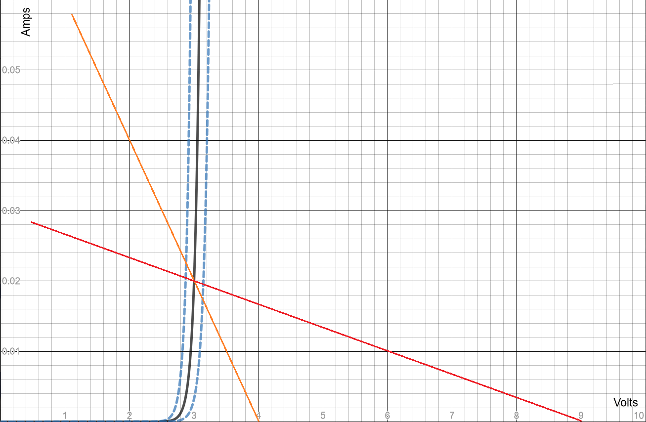
glen_geek mentioned the use of a ballast resistor as your current-limiting device. I've written elsewhere about this: why does an LED always need a resistor and how can Ohms law be used to calculate the resistor value for an LED. Let's take a look at a single LED (this is a \$3\:\text{V}\$ typical when operating at \$20\:\text{mA}\$ example case):
enter image description here

Here, I'm showing three exponential curves that illustrate the variation I've chosen for LEDs that may be drawn out of a bag. I'm also showing two values for \$V_\text{CC}\$, \$4\:\text{V}\$ and \$9\:\text{V}\$, with the load lines for resistors that were chosen in order to hit \$20\:\text{mA}\$ on the middle curve (the "typical" LED case.) You can easily see that a higher \$V_\text{CC}\$ selects a different resistor slope and exhibits a much smaller variation in LED current vs variations in those LEDs.

The above is just one LED in a string. If you place \$N\$ of them in series there will be a distribution around the typical values and while random chance will likely prevent the very worst cases from happening, you can probably expect the string voltage's standard deviation to be \$\sigma_{_\text{STRING}}=\sqrt{N}\cdot\sigma_{_\text{LED}}\$.

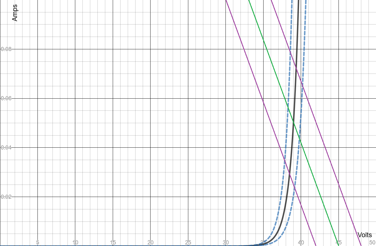
Let's say that at \$I_\text{LED}=50\:\text{mA}\$ you typically expect \$V_\text{LED}=3\:\text{V}\$. But suppose \$\sigma_{_\text{LED}}=60\:\text{mV}\$, as I proposed earlier. And suppose I wanted to use \$V_\text{CC}=45\:\text{V}\pm 3\:\text{V}\$, also as I proposed earlier. Then I could use, at most, 13 LEDs in a series. I'd expect random selections into series strings to yield \$\sigma_{_\text{STRING}}=\sqrt{13}\cdot 60\:\text{mV}\approx 216\:\text{mV}\$. So \$3\,\sigma\approx 650\:\text{mV}\$.

If I design a ballast resistor on the basis of the assumed \$V_\text{CC}=45\:\text{V}\$ (I have to pick some value) then I'd come up with the green line below:
enter image description here

The purple lines use the same slope (because the resistor doesn't dynamically change itself) and show what happens under the ripple I considered before. I think you can see that this suggests I would need to seriously re-consider and perhaps choose a much more regulated voltage supply. The ripple I was earlier considering wrecks havoc on regulation, given the small voltage overheads I'm working with.

You could fix this by using fewer LEDs in each string and therefore reserving more voltage overhead for the resistors. But then this is more LED strings and you are wasting more power in those resistors, too.

All in all, I think this is a pretty strong argument against the idea that glen_geek suggested -- just using a ballast resistor. And it is a strong argument for using a low-overhead active current regulation circuit.

Current Regulation Thoughts

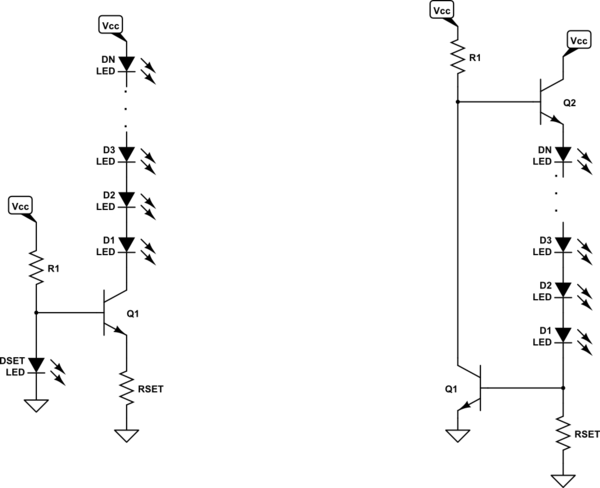
Let's get straight to it. Don't bother with an opamp. Just use BJTs. Here's by suggestions:
schematic

simulate this circuit – Schematic created using CircuitLab

In the left side circuit, I am using an LED (doesn't need a lot of current in it, though -- perhaps a few milliamps?) called DSET in the schematic in order to set the voltage at the base of the transistor. (A GaAsP LED type used with a BJT can be remarkably temperature-stable.) Using \$V_{\text{LED}_\text{REF}}\$ to represent the voltage across DSET, the calculations are \$R_\text{SET}=\frac{V_{\text{LED}_\text{REF}}-V_\text{BE}}{I_\text{LED}}\$ and, if you are considering \$50\:\text{mA}\$ per string, then \$R_1=\frac{V_\text{CC}-V_{\text{LED}_\text{REF}}}{2\:\text{mA}}\$ (the \$2\:\text{mA}\$ should be enough to keep DSET operating well and also provide enough base current to operate \$Q_1\$.)

The right side circuit is does experience variation with temperature (on \$V_\text{BE}\$ of \$Q_1\$.) But overall this is on the order of maybe \$-0.3\:\frac{\%}{^\circ\text{C}}\$ for changes in the current. Probably acceptable. The calculations are \$R_\text{SET}=\frac{V_\text{BE}}{I_\text{LED}}\$ and \$R_1\approx\beta_2\cdot \frac{V_{\text{CC}_\text{MIN}}-2\cdot V_\text{BE}-N\cdot V_\text{LED}}{I_\text{LED}}\$.

Summary

Get and use an isolation transformer. Select a secondary voltage and work out the number of LEDs you can support per string. Use a bridge rectifier and filter capacitors to keep the ripple down to some minimum. You may also want to consider some method of current in-rush limiting, at power-on.

There are some ideas I could add to the above, if it is your desire that only a single resistor determines the current in all of the strings. It's probably not necessary to do that, though. (Which is why I didn't draw it out.)

Yes, the above arrangement of 13 LEDs per series string means 8 strings of LEDs and nominally \$400\:\text{mA}\$, when summed, that the transformer must support. But I think it's safer. (You could follow "Harper - Reinstate Monica"'s suggestion and still further increase the number of strings.) But this means less worry.

By the way, I still haven't addressed any of the above to single-point failures. How do resistors tend to fail? How do LEDs tend to fail? How does a BJT tend to fail? How would a failure of any one of these parts affect the circuit? What might you do to mitigate these issues? I'm leaving that for your thoughts.
\$\endgroup\$
2
\$\begingroup\$

I will assume that you have thought through the safety of your product, and won't be electrocuting your users.

Bear in mind that if you rectify 110V AC, you will get a peak voltage of around 155V. the LEDs will not conduct when the rectified AC is below about 100V, and so will only be on for part of each cycle. Once they do start to conduct, your current limiter may be dropping a significant voltage, perhaps 55V at the peaks. If your AC is actually 120V, then the peaks go up to 170V.

So there's a possibility of horrible flicker, until the current limiter overheats and fails.

Better LED lamps tend to smooth the rectified AC, to reduce the flicker to something more acceptable. That tends to push the voltage up to the peak value for a longer part of the waveform, and needs to be allowed for in the design.

\$\endgroup\$
1
\$\begingroup\$
  1. I search for this kind of implimantation on the internet but was not able to find anything like this, and it is a fairly simple approach but why are manufacturers avoiding this kind of approach for high count LEDs in Series. Is there something I am missing?

Well, yes.

First, simply rectifying a 110 VAC and using it is wildly dangerous. It's the sort of thing you can do if you have full control of where the wiring goes, such as inside a light fixture or appliance. Using it for an uncontrolled (by the controller manufacturer) installation is just asking for liability issues. When jonk says to use an isolation transformer he's not just whistling Dixie, and this will greatly increase the size and weight of your controller.

Second, CC sources are not usually limited to your goal of 200 ma, nor are they produced for a specific number of LEDs. As a result, a linear regulator will need a pass element which can handle both high current and high voltage across the pass element if a few high-current LEDs are used.

Look here for a listing of what you can actually expect in terms of power line standards. Note that "110" is actually a nominal 120 VAC, and you can expect occasional excursions in the range of 104 to 127 volts at the socket.

Now, consider what happens at 127 volts - you'll have 25 volts across the pass element, for a pass element power of 5 watts. That's probably not an issue, right? (You were happy with 5.6) Well, if a regulator manufacturer were willing to produce only a 200 mA current, it would be. Problem is, LEDs used for illumination will typically run at several amps. Let's say three amps. Then your pass element is going to need to dissipate 75 watts. That is not going to be either small or light (or cool). Ok, granted that at the higher currents your LED voltage will be higher, which reduces the pass element voltage, but the total effect requires careful attention.

So I personally think that in this case the Linear Approach offers a lot of advantages like very low EMI, low flicker and can be made compact as well because space is limited.

Well, sure. For your particular case. Sort of. Your flicker frequency will be 120 Hz, and that is still in the problematic range. After all, it's the flicker frequency of fluorescent bulbs, and nobody says their quality is great. Your unit can only be small because you're using quite low currents and effectively rather low brightness with a lot of LEDs. There simply isn't much market for this useage, and more normal requirements will use fewer, brighter LEDs, and all your advantages disappear in this case.

\$\endgroup\$

Your Answer

By clicking “Post Your Answer”, you agree to our terms of service and acknowledge you have read our privacy policy.

Not the answer you're looking for? Browse other questions tagged or ask your own question.