6
\$\begingroup\$

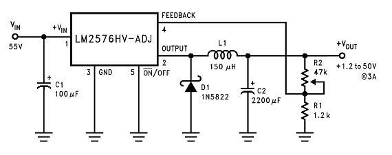
I have a simple pre-made buck converter that looks something like this:

https://www.hobby-hour.com/electronics/lm2576hv-adj-buck-regulator-schematic.png

The output voltage can be easily adjusted, by turning the R2 trimpot, which adjusts the voltage the feedback pin is getting.

What I would like to do, is to take this mechanical way of setting the output voltage and change it to a digital one, where I can set the output voltage I want with something like an Arduino.

My first idea was to simply rip out the R2 trimpot and replace it with a digital potentiometer, but this turned out to be a no-go, since the digital pots I have (and most cheap digi pots I have seen) have voltage limits of around 0 - 5V, and I will be outputting voltages between 1.2 - 23V (The power source feeding the buck is 24V)

My second idea would be to somehow use an op amp to replace the R2 trimpot, but I have not been able to figure out how to go about this.

What would be some simple way to achieve my goal?

\$\endgroup\$
2
  • \$\begingroup\$ You could use Vout with a divider as Uref for a microcontroller with a DA output as feedback voltage. \$\endgroup\$
    – Mike
    Commented Dec 20, 2019 at 9:20
  • \$\begingroup\$ Nice idea... where the DAC serves as a digitally-controlled feedback network ("digipot"). \$\endgroup\$ Commented Dec 20, 2019 at 11:11

4 Answers 4

7
\$\begingroup\$

Put the digipot in R1's position. The max normal voltage seen at the FB pin will only be +1.25 volts so a 5 volt device will be fine. However, there might be fault circumstances when this might rise above 5 volts so put a zener diode across that point.

The other end of the digipot will be at 0 volts so this is another advantage. However, a digipot will introduce capacitance that may cause ringing in the regulator's output voltage and this might require you to have a small capacitor across R2 (about 47 pF).

You should also consider that using a digipot as a rheostat has two disadvantages: -

  • The end-to-end resistance of the pot isn't accurately defined so there will be a larger error than when using a conventional fixed resistor
  • Digipots are much better in terms of temperature stability when operated as a potentiometer rather than a rheostat.
\$\endgroup\$
2
  • \$\begingroup\$ As is, I turn R2 to provide the feedback pin with up to 23V, if I crank the wiper up, where the 47k is 0ohms (relative to FB). So the R1 is seeing 23V in the voltage division. In order to replace the R1 with a digital pot and have it work the same way, won't I still have to be able to deliver up to 23V to the FB pin, and thus expose R1 to 23V? \$\endgroup\$
    – Askerman
    Commented Dec 22, 2019 at 9:21
  • \$\begingroup\$ No, don’t be silly, the feedback pin regulates to about 1.25 volts. Only under some fault conditions will the feedback pin go significantly above 1.25 volts and that can be caught by a zener diode. Read the data sheet it specifically tells you what the FB pin has on it when in regulation. \$\endgroup\$
    – Andy aka
    Commented Dec 22, 2019 at 11:57
2
\$\begingroup\$

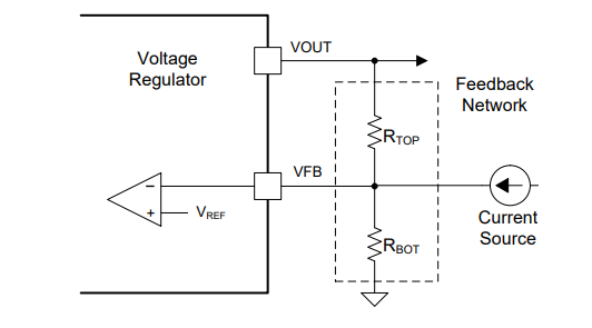
You can dynamically change the output voltage changing the gain of the network (Vfb/Vout) injecting/extracting a small amount of current in the feedback network. If you inject current to the feedback node the output voltage decreases. You can use a DAC and a current source (transistor) to accomplish this.

enter image description here

\$\endgroup\$
3
  • \$\begingroup\$ By "injecting/extracting a small amount of current in the feedback network" you do not "change the gain of the network (Vfb/Vout)"; you just add another input quantity (current) besides VREF. \$\endgroup\$ Commented Dec 20, 2019 at 10:45
  • 1
    \$\begingroup\$ Why not. If Vout would be equal to Vref ( 1 + Rtop/Rbot), increasing current is like inserting a virtual resistance in parallel with Rtop. Extracting current is like inserting a virtual resistance in parallel with Rbot. \$\endgroup\$
    – pantarhei
    Commented Dec 20, 2019 at 11:18
  • 1
    \$\begingroup\$ +1 for the ingeniuty! What you inserted in parallel to Rtop or Rbot, is a 'current-stabilizing nonlinear resistor' (aka current "source"). It behaves as a 'dynamic resistor' that injects/sinks constant current to/from the voltage divider output. To behave as a 'virtual ohmic resistor', its current should change proportionally to the voltage across it. So you do not change the ohmic resistance inserted in parallel to Rtop or Rbot; you change the current flowing in parallel to them. Your impact is not multiplicative (changing 1 + Rtop/Rbot); it is additive (adding another input voltage). \$\endgroup\$ Commented Dec 20, 2019 at 15:25
0
\$\begingroup\$

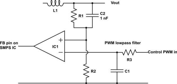
The circuit below allows Vout control using either PWM or an analog voltage.

R#/C1 form a low pass filter to convert PWM to DC.
To get low ripple it is usually desirable to have the filter corner frequency much lower than the PWM frequency. For more rapid response I often use a Bessel filter in this role. A 3 pole Bessel can be implemented with 1 opamp section and a 5 pole with 2 opamps. If a quad opamp is used the end result is cheap and compact.

IC1 acts as a comparator, comparing the user provided control voltage with voltage from the divided output voltage. An opamp can typically be used in this role without problems. IC1 here provides high/low output and this action is usually acceptable to SMPS ICs. If desired IC1 could be configured as a finite gain amplifier, allowing analog control of the FB pin, but this level of sophistication is not usually required.

schematic

simulate this circuit – Schematic created using CircuitLab

\$\endgroup\$
0
\$\begingroup\$

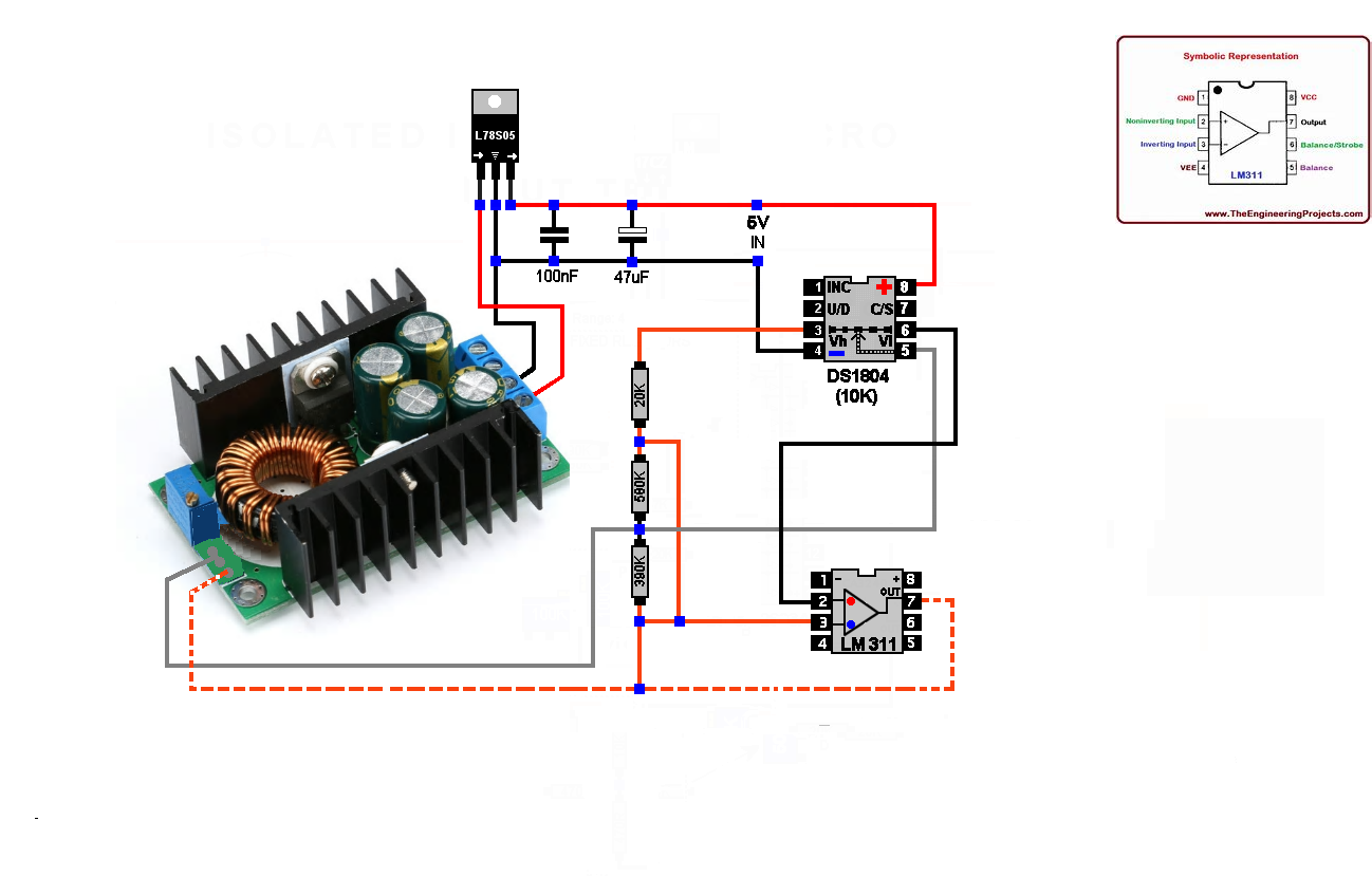
try this circuit. It worked for me after 3 weeks of testing and burning out components. It works fine from 4.1V to 23.5V. You need a 10K trimpot (DS1804) and an op amp (LM311). I tried with other op amps, but without success. Good luck.enter image description here

\$\endgroup\$
1
  • \$\begingroup\$ What voltage did you use to sypply LM311? Dual? Single? If dual did you also connect GND to pin 1? \$\endgroup\$
    – AKTanara
    Commented Dec 22, 2022 at 11:15

Your Answer

By clicking “Post Your Answer”, you agree to our terms of service and acknowledge you have read our privacy policy.

Not the answer you're looking for? Browse other questions tagged or ask your own question.