0
\$\begingroup\$

schematic

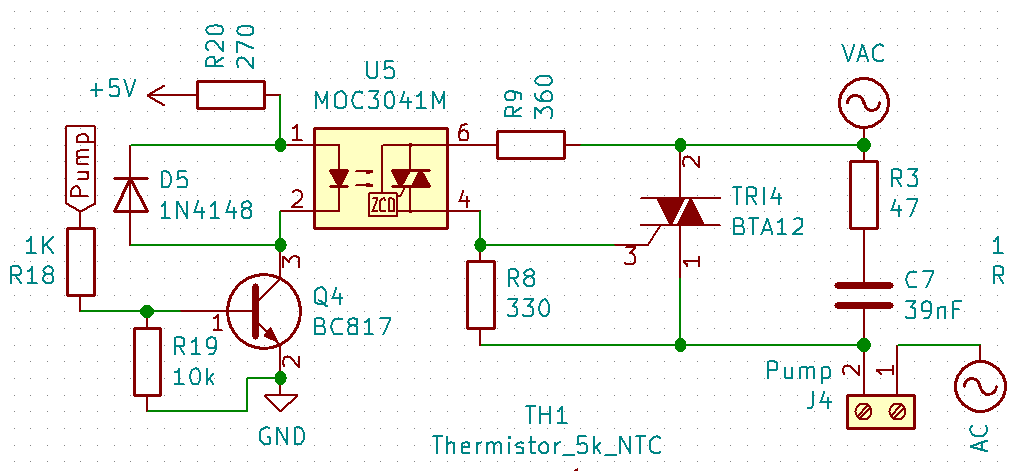
I'm using the circuit in the picture as a replacement for a mechanical relay running a 40 W, 220 V water pump.

The problem is that although the circuit seems to be correct, it doesn't work, and I'm getting a weird result on the multimeter.

When monitoring the AC output of the circuit with a multimeter, it shows 220 V when the logic input of the moc3042m is low. Also, this voltage doesn't turn on the pump. When changing the logic input to high (5 V), the output doesn't change.

  • The actual pump is connected to the J4 terminal.
  • The Pump label in the picture is for the logic input.

If you see any problem in the schematic, please explain it.

\$\endgroup\$
13
  • 1
    \$\begingroup\$ Are you measuring the voltage with pump and multimeter connected to J4 in parallel, or only multimeter? BTW: D5 is not needed here. \$\endgroup\$ Commented Jan 8, 2020 at 16:13
  • 1
    \$\begingroup\$ Have you tried using a lamp as the load? \$\endgroup\$
    – Andy aka
    Commented Jan 8, 2020 at 16:14
  • 2
    \$\begingroup\$ The circuit appears correct. The 220VAC multimeter measurement when 'off' is expected with the pump not connected because of the snubber network R3/C7. Carefully measure the voltage from pin 1 to 2 of U5 with the logic input high. It should be approximately 1.2VDC. You don't need VAC for the measurement. \$\endgroup\$ Commented Jan 8, 2020 at 16:27
  • 2
    \$\begingroup\$ Was it an LED lamp? If so, that sounds normal because the snubber lets thru enough current. \$\endgroup\$
    – Andy aka
    Commented Jan 8, 2020 at 20:21
  • 1
    \$\begingroup\$ Sounds normal. Test with an incandecent bulb as load in parallel to your multimeter. \$\endgroup\$
    – winny
    Commented Jul 31, 2020 at 12:46

2 Answers 2

-1
\$\begingroup\$

My opinion the circcuit is not that good.first if I were you I will try to connect pump before triac,Bta12 most efficient when 1 pin on negative rail.Moc 3041 is not ttl logic component it simple opto coupling ( led-diac) if the dropping voltage in between leg 1 and 2 is not enough for driving of led then diac will not work.My guess is your moc is not working propely.But again I would not use this circuit.

\$\endgroup\$
-2
\$\begingroup\$

I know this is Kind of answering late (AFTER ALMOST 3 YEARS) :D But I think this circuit is absolutely not correct. you see, the pump connected parallel to triac and this Cause the pump to be turn on even without "DRIVE PULSE" to its gate. so first of all connect the pump serial between the triac and AC supply voltage. Then, What is R8???? I mean, what was the purpose? if its a gate driver it must connect serial between second pin of secondary part of optotriac and the gate. finally connect pin 1 of triac to second pin of AC supply. tnx by :)

\$\endgroup\$
2
  • 2
    \$\begingroup\$ Did you mean "snubber"? The "pump" connector is clearly in series... \$\endgroup\$ Commented Oct 15, 2022 at 17:56
  • 1
    \$\begingroup\$ khalil seidali - Hi, A different account tried to make a major edit to your answer. If that was you, then please use the same account to do the edit as you used to write this answer. Otherwise we don't know that it is you and such a major edit should only be done by an answer's original author. If you want to delete your answer then you can do that, again using the original account. (On desktop browsers, you will see a "Delete" link below the answer. If you cannot see that, you can flag your answer and ask a moderator to delete it but, again, only from the original account.) Thanks. \$\endgroup\$
    – SamGibson
    Commented Oct 17, 2022 at 8:11

Your Answer

By clicking “Post Your Answer”, you agree to our terms of service and acknowledge you have read our privacy policy.

Not the answer you're looking for? Browse other questions tagged or ask your own question.