0
\$\begingroup\$

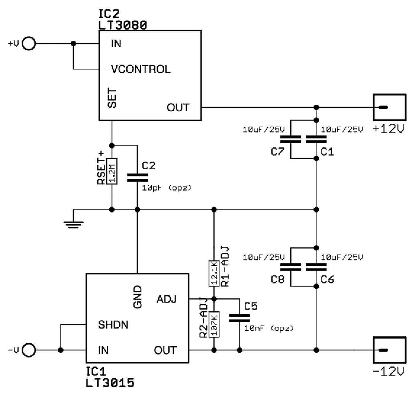
I designed a simple circuit around LT3080 (positive linear regulator) and LT3015 (negative linear regulator).

LT3015 datasheet

I'm feeding them with +19V and -19V (input bypass caps not show)

enter image description here

the positive rail is fine, the problem is that the negative rail is not regulating at all, since I'm getting -19V on the output of the LT3015, not only when the PSU is floating, but also when I connect this PSU with the circuit I need to supply.

My hypothesis is that the supplied circuit is not providing enough load for the regulator.

But unfortunately I can't understand, reading the datasheet, if this is the case, and how could I fix that. Also I'm not aware of the mA needed by the supplied circuit, but since the -12V rail is only used by a TL074 opamp (that probably is now fried after the PSU supplied -19V), I guess I can at least understand the worst case.

\$\endgroup\$
4
  • \$\begingroup\$ Show pin numbers and describe the physical part type \$\endgroup\$
    – Andy aka
    Commented Jan 26, 2020 at 20:11
  • \$\begingroup\$ well, the TL074 is nothing I'd cry over too much – things are cheap and really old (hint: there's better opamps that these, and unless you really have a signal that needs to swing around ground for some reason, having a negative supply seems way overkill. Instead, biasing to a positive voltage and using an RRIO opamp would probably do.) \$\endgroup\$ Commented Jan 26, 2020 at 20:21
  • \$\begingroup\$ I used Q PACKAGE 5-LEAD PLASTIC DD-PAK, as shown on page 2 of the datasheet \$\endgroup\$ Commented Jan 27, 2020 at 18:36
  • \$\begingroup\$ Did you get this fixed? \$\endgroup\$ Commented May 11 at 17:59

1 Answer 1

0
\$\begingroup\$

The first obvious question is: is it wired correctly to the diagram? Secondly, are there any poor soldered joints? Thirdly, are the resistor values correct? These resistors are special values and will have at least 4 colour bands or have they been made up of various other resistors which may not result in the desired value. It suggests that R2 is much higher than it should be or an open circuit; this would result in the adjust reference being too low and the device will try to pump more output in order to try to raise the voltage to 1.22 V.

You don't mention the input voltage you are using. Disconnect both trim resistors and measure their value with an accurate multimeter. You could try using 100k for the 107k and 12k for the 12.1k -- this should give an output of 11.38 V or with 11k for the 12.1k will give 12.31 V, which is plenty close enough for an op amp.

\$\endgroup\$

Your Answer

By clicking “Post Your Answer”, you agree to our terms of service and acknowledge you have read our privacy policy.

Not the answer you're looking for? Browse other questions tagged or ask your own question.