I saw a video where a person wired a resistor to the outer pins of a potentiometer to lower the resistance. Does this work? And if it does, can I still use the wiper and an outer pin with it lowered? Here is the video for reference https://www.youtube.com/watch?v=W-TmOLPDLhc&t=66s.
-
3\$\begingroup\$ Yes it works. Look up parallel resistances and note whether the larger or smaller one dominates as the values get very different. Not that linearity is NOT maintained. \$\endgroup\$– DKNguyenCommented Jan 31, 2020 at 15:04
-
\$\begingroup\$ @DKNguyen Oh, hello. Why didn't you answer this question in the other post? \$\endgroup\$– EmeraldVoltsCommented Feb 1, 2020 at 3:54
-
\$\begingroup\$ @DKNguyen So if I use one of those calculators, would they be accurate? I tried one with the original pot being 500 ohms, and the resistor being 3 ohms, and it said something around 3 ohms. So if I wire a 3 ohm resistor to the outer pins of a 500 ohm pot, would it actually be around 3 ohms max if I use the wiper and one other pin? \$\endgroup\$– EmeraldVoltsCommented Feb 1, 2020 at 3:56
-
1\$\begingroup\$ @Circuitfantasist By some of the outer pins, do you mean one of them? \$\endgroup\$– EmeraldVoltsCommented Feb 1, 2020 at 16:05
-
1\$\begingroup\$ @Circuitfantasist Ok, thank you! \$\endgroup\$– EmeraldVoltsCommented Feb 2, 2020 at 16:34
1 Answer
I saw a video where a person wired a resistor to the outer pins of a potentiometer to lower the resistance. Does this work?

simulate this circuit – Schematic created using CircuitLab
Figure 1. (a) R1 has no effect on the potentiometer. (b) R5 does have an effect on the potentiometer.
- In Figure 1a the potentiometer is driven by the preceding amplifier which will use negative feedback (not shown) to drive the output to the desired level. Adding R2 makes no difference in this case other than to waste power.
- In Figure 1b R4 and R3 form their own potential divider which limits the voltage when R3 is at the "max" position. The max value will depend on the ratio of R4 to R3. By adding R5 in parallel with the potentiometer we cause a greater voltage drop across R4 and this again decreases the maximum output of the potentiometer.
The overall effect will also depend on what impedance is connected to OUT.
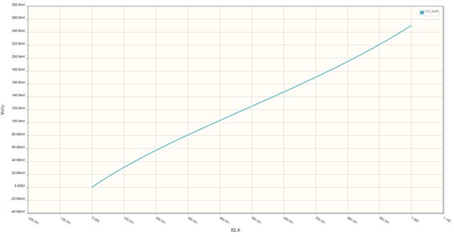
You can model this in a spreadsheet using the series and parallel resistance formulas. Alternatively set it up in a simulator such as CircuitLab (available on the editor toolbar on this site) and do a sweep simulation. In Figure 2 I've run a DC sweep on R2.K (the wiper position) and obtained the result of Figure 3.

Figure 2. Circuit for simulation.
Figure 3. Results of simulation.
Note the non-linearity as a result of the relatively high load of R4.
-
\$\begingroup\$ Sorry, I'm kinda a beginner, could you simplify that for me please? \$\endgroup\$ Commented Feb 1, 2020 at 3:53
-
\$\begingroup\$ I'll do that if you'll edit your question to explain what you are trying to achieve. \$\endgroup\$ Commented Feb 1, 2020 at 9:02
-
\$\begingroup\$ I just want to lower the resistance of a pot, since the low resistance ones are more expensive. \$\endgroup\$ Commented Feb 1, 2020 at 16:04
-
\$\begingroup\$ Why? What value? For what application? Where in the circuit? Usually pots are available in a wide range of values for a particular style and all are the same price. Again, put all the information in your question where everyone will see it. \$\endgroup\$ Commented Feb 1, 2020 at 16:13
-
\$\begingroup\$ The other person on this post already told me what I needed. I needed something around 3 ohms, and the lowest I found was 10 ohms, cheapest being $2.25 \$\endgroup\$ Commented Feb 1, 2020 at 21:54

