1
\$\begingroup\$

I have a 12-24 V dimmer for LED strips like this: https://www.circuitlab.com/editor/#?id=c8m48y
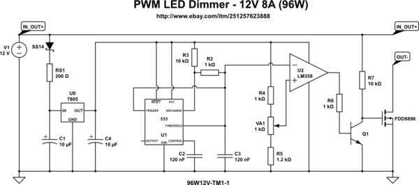
schematic

simulate this circuit – Schematic created using CircuitLab

I want to understand a couple of issues about it:

  1. Does it utilize only 1 channel of LM358?
  2. Copying the schematic analogous to R4, VA1, R5, R6, R7, Q1 and MOSFET to a second channel (unit) of LM358 I can get the second dimmable channel for another LED strip? If yes - would it be also up to 8A?
  3. I can use the same output after R2 as a negative input to the second channel of LM358?
  4. What is the PWM frequency? \$ 1 / ( C3 * R2) \$ or \$1 / ( C3 * ( R3 + R2))\$ ?

Thank you!

\$\endgroup\$
3
  • \$\begingroup\$ All those ICs work better running off 12V \$\endgroup\$ Commented Feb 4, 2020 at 5:24
  • 1
    \$\begingroup\$ 12V - yes, but NE555 can't handle 24V. Its maximum is up to 18V, and 16V is suggested as maximum for long-term operation page 4 of datasheet \$\endgroup\$ Commented Feb 4, 2020 at 15:35
  • \$\begingroup\$ ah, right,I just read the title,and the schematic, not the product description... still 7809 or 7810 would be an improvement, \$\endgroup\$ Commented Feb 4, 2020 at 20:32

1 Answer 1

2
\$\begingroup\$
  1. Yes it only uses one of the op-amps and there are two in the same package.
  2. Assuming your power supply can handle the power drawn from them then yes. As long as you don't hook up the LED strip to the same MOSFET.
  3. Yup, Op-amps have infinite input impedance so they won't effect your circuit.*
  4. I believe the frequency won't be either of the ones you state. However I may be wrong.

\begin{align} t_{dicharge} &= (0.693 * C3 * R2 * R3) \\ t_{discharge} &= (0.693 * 2 * R2) \end{align}

adding them together

\begin{align} T &= 0.693 * C3 * (R3 + 2*R2) \end{align}

convert to frequecny

\begin{align} F &= \frac{1}{T} = \frac{1}{(0.693 C3 (R3 + 2R2))} \end{align}

*Well, high enough that it shouldn't effect your case.

\$\endgroup\$
5
  • \$\begingroup\$ swapping the inverting and non inverting inputs for the second channel will reduce the amount input of current ripple (vs having them the same) wire the potentiometer backwards to compensate. \$\endgroup\$ Commented Feb 4, 2020 at 5:29
  • 1
    \$\begingroup\$ @nootnootmachine, MathJAX tip: use \times for multiplication. In regular post text you can use × HTML entity along with &Omega', ω, μ, etc. (but it doesn't work in the comments). \$\endgroup\$
    – Transistor
    Commented Feb 4, 2020 at 8:28
  • \$\begingroup\$ Thank you! I also found a similar module but it doesn't have a transistor before MOSFET. The output of LM358 is directly connected to MOSFET. Is it safe or it should have a transistor? \$\endgroup\$ Commented Feb 4, 2020 at 15:40
  • \$\begingroup\$ @Transistor thanks for your help \$\endgroup\$ Commented Feb 4, 2020 at 21:16
  • \$\begingroup\$ @Yehor yes that is fine as long as you put in a resistor to limit the current. The output in 40mA from the opamp so if you put in resistor between the opamp and transistor so it dosnt get above 40mA you will safe gaurd the opamp. Assuming 5V coming out of the op-amp. 5 / 40mA = 125 ohms minimum. \$\endgroup\$ Commented Feb 4, 2020 at 21:21

Your Answer

By clicking “Post Your Answer”, you agree to our terms of service and acknowledge you have read our privacy policy.

Not the answer you're looking for? Browse other questions tagged or ask your own question.