0
\$\begingroup\$

community! I have a problem as follows. I've been trying to interface the LM19 temperature sensor using Arduino. I made a function to read and compute the temperature from the sensor according to a formula described in its datasheet. The result was pretty good. However, when I added another function for reading ADC value from an LDR, the result of the temperature computation went crazy!!! Here's my code:

/*
 Author: M. Chenda
 Created on Tue Feb 18, 2020
*/

#define ldr 0       // assign LDR's pin to analog pin A0
#define light 8     // assign LED's pin to digital pin 8
#define lm19 2      // assign LM19's pin to analog pin A2

int ldr_val = 0;    // LDR's ADC reading variable
String state;       // string representing light's state

int lm19_val = 0;   // LM19's ADC reading variable
float Vo = 0.00;    // V output of LM19
float temp = 0.00;  // temperature variable

void setup() {
    pinMode(light, OUTPUT);
    Serial.begin(9600);
    while(!Serial) {;}  // wait for serial port connection
}

void loop() {
    lighting();
    temp_control();
    delay(500);
}

/*  LIGHT CONTROL   */
void lighting() {
    ldr_val = analogRead(ldr);  // read LDR's ADC value (brightness)
    if (ldr_val < 512) {
        digitalWrite(light, LOW);
        state = "off";
    }
    else {
        digitalWrite(light, HIGH);
        state = "on";
    }
    Serial.print("LDR's ADC:  ");
    Serial.println(ldr_val);
}

/*  VALUE MAPPING FUNCTION  */
float mapping(float x, float in_min, float in_max, float out_min, float out_max) {
    return (x - in_min) * (out_max - out_min) / (in_max - in_min) + out_min;
}

/*  TEMPERATURE MEASUREMENT */
void temp_control() {
    // read LM19's ADC value
    lm19_val = analogRead(lm19);
    // convert the ADC value to voltage (0 to 5V)
    Vo = mapping(lm19_val, 0, 1023, 0, 5);
    // compute temperature value in Celsius
    temp = -1481.96 + sqrt((2.1962*pow(10,6))+((1.8639-Vo)/(3.88*pow(10,-6))));
    Serial.print("      Temperature (Celsius):  ");
    Serial.println(temp);   // print the measured temperature to Serial Terminal
}

enter image description here What could be the root of this problem?

\$\endgroup\$
6
  • \$\begingroup\$ Your code could be faultless but if you connect / use the LDR in the wrong way then it will not work anyway. You need to include a schematic to show how you have connected things. What works with an LM19 will not work with an LDR unless you add a circuit that will output a similar as the LM19 does. \$\endgroup\$ Commented Feb 18, 2020 at 7:23
  • \$\begingroup\$ Please share the connection diagram, also state what went wrong.. saying crazy means nothing to solve the problems.. was there offset observed? If yes how much. Was there random values sometimes and normal operation.. does commenting the control section eliminates the problem? \$\endgroup\$
    – User323693
    Commented Feb 18, 2020 at 7:55
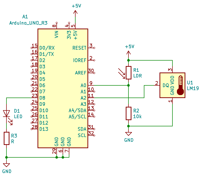
  • \$\begingroup\$ @Bimpelrekkie I added a quick reference of my schematic. Please take a look. Also, I want to mention that lighting() function works correctly either lighting() and temp_control() functions are called or only lighting() itself is called. \$\endgroup\$
    – M. Chenda
    Commented Feb 18, 2020 at 8:08
  • \$\begingroup\$ @User323693 I've just added a quick reference of my schematic. Please take a look. What went wrong is that when I added the lighting() function in the loop(), I received random values of temp from temp_control() function. And yes, when I commented out the lighting() function, my temperature computation function worked correctly again. \$\endgroup\$
    – M. Chenda
    Commented Feb 18, 2020 at 8:16
  • 1
    \$\begingroup\$ How long are the wires to the LM19? Is the "quick reference" schematic exact as-built? For example, are there any capacitors that are not shown in the schematic? Finally, what happens when you read ADC 2x for each input and discard the first measurement? \$\endgroup\$ Commented Feb 18, 2020 at 9:06

3 Answers 3

0
\$\begingroup\$

When you change channels the input section of the ADC requires a bit of time (depending on the source impedance and the difference between the previous and new voltages) for the reading to settle to the new value. Adding a delay or discarding the first reading of the new channel can mitigate that effect.


Edit: To be useful, the delay would have to be inserted after setting the multiplexer but before initiating the ADC read, so inside the analogRead function. If you look at the source code, there is a commented-out delay.

Maybe this is a FAQ in the Arduino community.


Don't forget to pay attention to the capacitance loading notes on the temperature sensor if you extend the least, they are not tolerant of capactive loading beyond a couple hundred pF and can oscillate or ring.

\$\endgroup\$
1
  • \$\begingroup\$ I tried adding a delay for each ADC reading, but it didn't work. However, repeating the ADC reading for each channel actually works. Thank you! \$\endgroup\$
    – M. Chenda
    Commented Feb 18, 2020 at 16:42
1
\$\begingroup\$

The ADC has a built in capacitor at it's input. So, you should allow the capacitor to charge slowly to the actual value. If there is high resistance (LDR), it will take more time to charge.
Since, you are switching the ADC to different channels, you should give sufficient time for the ADC sampling capacitor to charge.

Provide sufficient delay after choosing the channel - OR read the ADC several times, and consider the last couple of values once the values are stable. You can read once, give a delay, and do a second read.

\$\endgroup\$
1
  • \$\begingroup\$ I tried adding a delay for each ADC reading, but it didn't work (plus, I can't afford to slow down the execution of my instructions). However, repeating the ADC reading for each channel actually works. Thank you! \$\endgroup\$
    – M. Chenda
    Commented Feb 18, 2020 at 16:46
0
\$\begingroup\$

A minor thing but I would suggest changing

#define ldr 0       // assign LDR's pin to analog pin A0
#define light 8     // assign LED's pin to digital pin 8
#define lm19 2      // assign LM19's pin to analog pin A2

to

#define ldr A0       // assign LDR's pin to analog pin A0
#define light 8     // assign LED's pin to digital pin 8
#define lm19 A2      // assign LM19's pin to analog pin A2

I don't expect it will solve your issues (and I can't see any issue with your code) but it is good practice to use the channel numbers.

Further reading on the subject: analogRead(0) or analogRead(A0)

\$\endgroup\$
1
  • \$\begingroup\$ It isn't really the root of my problem, but thank you for your comment anyway! Cheer! \$\endgroup\$
    – M. Chenda
    Commented Feb 18, 2020 at 16:32

Your Answer

By clicking “Post Your Answer”, you agree to our terms of service and acknowledge you have read our privacy policy.

Not the answer you're looking for? Browse other questions tagged or ask your own question.