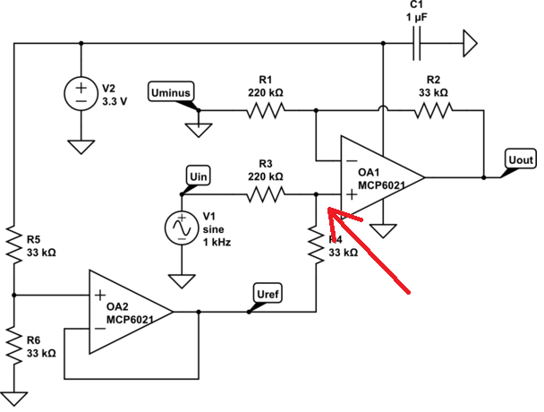
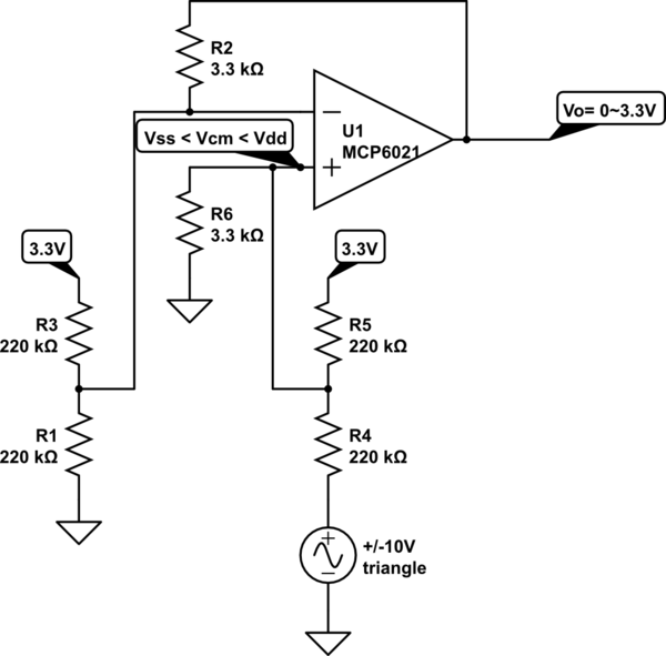
I need to convert +/- 10 V sine to 0...3.3 V sine. I made a circuit from this topic How to change -10;10V sine wave to 0;3.3V dor ADC
The one with two MCP6021's.
The problem is that at some point some irregularities happen

In this spot when I checked with oscilloscope it looked like it's cutting off bottom half of the sine instead of raising it with 1.65 V.
Could anyone explain the issue to me please?
In simulations it works fine, but in reality it doesn't.

