0
\$\begingroup\$

sorry in advance as english is not my mother tongue.

I have been using electron flow point of view for ages for analyzing and designing circuits (disclaimer: I have a background in computing - not electronics), learning with Floyd "electron flow" version and it's been working great... until I met flyback converters...

In all documents I have been reading, they all basically say, in a nutshell, that in the primary, when the switch is on, energy is stored in the transformer core - which acts like a simple coil - and that no current is flowing in the secondary, and as soon as the switch is off, polarity reverses on the secondary, and current flows.

It's all based on conventional current paradigm. Now if we take the electron flow point of view, there are some problems.

  1. Electron can not flow on the primary and not on the secondary at the same time. Otherwise, any transformer with no load on the secondary would have a strong current on the primary and burn.

  2. Regarding the secondary diode which is said to "block" the current while the primary is on, it clearly shows that the electrons can flow - because conventional current is the opposite of electron flow. Electrons are indeed charging the capacitor. When the primary is switched off, then the electrons are blocked by the diode and have only one way to flow: to the load.

It seems very strange to me that virtually all flyback papers say that energy is stored in the transformer core, whereas electrons are all gently stored in the capacitor on the secondary side....

Am I completely wrong or what? I am a bit puzzled actually by the fact that conventional current view can be very misleading when compared to reality ...

All comments welcome. Thanks a lot.

\$\endgroup\$
6
  • 3
    \$\begingroup\$ All our diode, transistors, thyristors, etc., have symbols whose arrows are based on conventional current flow. Switching to electron flow is going to cause you a lot of confusion. You can safely work with conventional current and "charge" rather than electron storage and get the right results. You will also be able to communicate clearly with other engineers. It might help if you add a schematic diagram of the circuit you are discussing into your question. There is an edit link below your question. Your English is much better than many of our native English writers! Welcome to EE.SE. \$\endgroup\$
    – Transistor
    Commented Apr 12, 2020 at 19:53
  • \$\begingroup\$ Nothing changes if you define current opposite to conventional current- It's just a convention. No current by either definition flows in the secondary in a conventional transformer with the secondary open. No current flows in a coupled inductor ("flyback transformer") in a flyback topology when the primary is on, and magnetic energy is stored in the magnetic field in the gap of the transformer. \$\endgroup\$
    – John D
    Commented Apr 12, 2020 at 19:56
  • \$\begingroup\$ Thanks for your answers. I know it is confusion-prone, but I can't get used to conventional current. In computers, a bit is a bit and a byte is a byte so I like to stick to reality. It's probably a slippery slope to try to understand both conventional current and electron flow versions, but if both are right, they should converge... hopefully. \$\endgroup\$
    – Necklondon
    Commented Apr 12, 2020 at 20:43
  • 1
    \$\begingroup\$ @Necklondon It's no different than if you decided than if you were using ones complement notation, with the exception that a '1' in the sign position you chose to make "+" and a "0" you chose as "-". Others might be confused when you called an ASCII 'A' (65, decimal to us "normal folks" but -65 from your new perspective) the value of -65. Some might be confused. But you'd both be talking about the exact same binary bits, either way. If you stick with the convention, you get past that part of communication and can proceed with more important communication, without dithering on notation details. \$\endgroup\$
    – jonk
    Commented Apr 12, 2020 at 21:47
  • 4
    \$\begingroup\$ Side note: In science/eng we have to confront reality. That's why we use conventional current, rather than integrating the pattern of free charge-density times drift velocity. Also, we measure volts, rather than trying to path-integrate the e-field itself. Also, we get our watts from V*I, not from the Poynting field. In truth, "actual reality" must be concealed with simplified concepts. After all, we cannot guarantee the nature of charge-carriers in circuits (often its electrons, but sometimes it's proton-flow in acid, or ion-flow in tissue.) "Conventional" current applies to all. \$\endgroup\$
    – wbeaty
    Commented Apr 12, 2020 at 21:51

2 Answers 2

1
\$\begingroup\$

Electron can not flow on the primary and not on the secondary at the same time. Otherwise, any transformer with no load on the secondary would have a strong current on the primary and burn.

Incorrect. All transformers take a moderate primary current (called the magnetization current) in order to produce an alternating flux that, in turn, induces the secondary voltage. This has nothing to do with load currents and is EVERYTHING to do with how flyback transformers work. It is this current that represents the energy stored in the core and, when the primary is disconnected, it is the same current (modified by the turns ratio) that flows into the capacitor and load via the diode.

Regarding the secondary diode which is said to "block" the current while the primary is on, it clearly shows that the electrons can flow - because conventional current is the opposite of electron flow. Electrons are indeed charging the capacitor. When the primary is switched off, then the electrons are blocked by the diode and have only one way to flow: to the load.

The diode blocks for sure and it can only be your analysis that is at fault. I don't know how to explain this in simpler terms other than you are mistaken in your analysis.

Am I completely wrong or what?

I'm afraid you are.

All comments welcome. Thanks a lot.

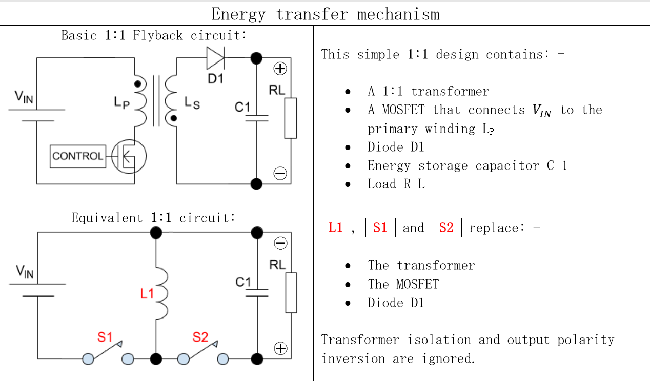
Given the disputed operation of a flyback converter in the comments, I'm adding a simple schematic of one for further discussion and clarification: -

enter image description here

\$\endgroup\$
6
  • \$\begingroup\$ My first sentence (that you state as incorrect) makes sense only when the secondary is not an open circuit, of course, as electrons won't jump. But in the flyback topology, the diode in the secondary is biased in such a way that electrons can flow when the magnetization current flows in the primary. So the situation is not as you describe. Should the diode have been reversed, I would understand. \$\endgroup\$
    – Necklondon
    Commented Apr 13, 2020 at 18:06
  • \$\begingroup\$ @Necklondon No, not true. The diode in the secondary is there to entirely ensure that there is no secondary current when magnetization current flows into the primary. Have you heard of transformer coil dot notation? This is the whole point about flyback transformers. If you are unsure then please link to a typical flyback circuit and I will explain why. \$\endgroup\$
    – Andy aka
    Commented Apr 13, 2020 at 18:19
  • \$\begingroup\$ Thanks for the schematic. I am perfectly aware of the opposite dot notation. In the primary, electrons flow from the bottom to the top. Hence, in the secondary, electrons flow from the top to the bottom. The diode allows "conventional current" from bottom to top, therefore it allows electrons to flow from top to bottom. \$\endgroup\$
    – Necklondon
    Commented Apr 13, 2020 at 19:00
  • \$\begingroup\$ @Necklondon The dot notation is about voltage polarity, thus if the switch is ON the current will flow through the primary winding. But no current will flow in a secondary winding because of the secondary voltage polarity doesn't allow the diode to conduct current. As try to show it here i.sstatic.net/BBb9r.png (the voltage polarity). \$\endgroup\$
    – G36
    Commented Apr 13, 2020 at 19:29
  • \$\begingroup\$ I am sorry, but your ref shows exactly what I am saying: electrons flow from bottom to top in the primary (from minus to plus), and the opposite in the secondary at the same time. The diode does not block them (the diode symbol is the opposite of the electron flow). So it is no surprise for me. \$\endgroup\$
    – Necklondon
    Commented Apr 13, 2020 at 19:42
0
\$\begingroup\$

I think I understand where the confusion comes from. On the primary side, the transformer coil is a load. Therefore, electrons flow from negative to positive. On the secondary side, the transformer coil is a generator, therefore, electrons do NOT flow THROUGH the coil from the negative to the positive, but from FROM the negative THROUGH the circuit TO the positive side. Hence the confusion Thanks to all constructive comments though.

\$\endgroup\$
1
  • \$\begingroup\$ I'm glad you got sorted. Accept one of the answers (even your own after about 8 hours, I think) to indicate that your question is answered. \$\endgroup\$
    – Transistor
    Commented Apr 13, 2020 at 21:20

Your Answer

By clicking “Post Your Answer”, you agree to our terms of service and acknowledge you have read our privacy policy.

Not the answer you're looking for? Browse other questions tagged or ask your own question.