0
\$\begingroup\$

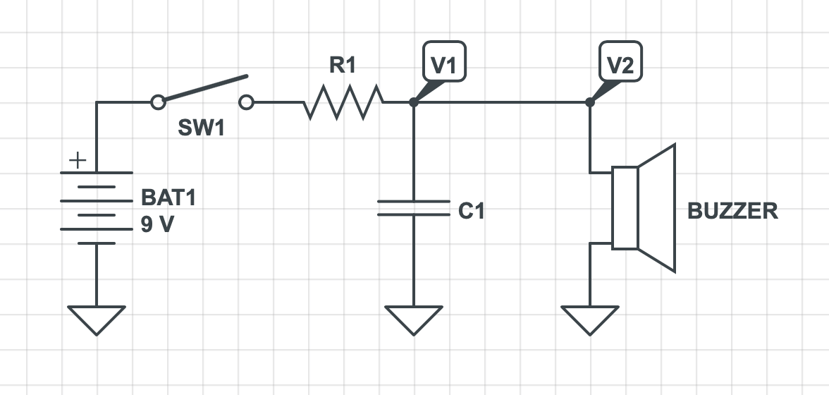
I'm working through Electronics for Dummies book and I'm stumped with the RC Timer example. See the diagram below. I believe I understand the idea of it taking a period of time for the capacitor to charge and that once it has charged sufficiently (i.e. the voltage it has is sufficient to drive the buzzer) then the buzzer sounds.

The bit I don't understand is why V1 and V2 in the diagram are not 9v instantly (ignoring the voltage drop across R1) as they would be in other parallel circuits.

Clearly I'm missing something fundamental in my understanding...

Thanks

enter image description here

\$\endgroup\$

2 Answers 2

4
\$\begingroup\$

The bit I don't understand is why V1 and V2 in the diagram are not 9v instantly (ignoring the voltage drop across R1)

Well if you ignore the volt drop across R1 then of course V1 and V2 (the same node) will be 9 volts the instant SW1 closes and infinite current will flow into capacitor C1.

So, ignoring stuff usually gets you the wrong answer.

The better answer is that after some length of time voltage V1 will be a steady DC voltage that is somewhat less than 9 volts. That is due to R1 dropping a voltage due to the potential divider formed by it (R1) and the resistance of the buzzer (RB). Let's say that (for the sake of argument) the voltage eventually reached is (say) 7 volts.

Then the actual voltage over time (v(t)) after the switch closes is: -

$$V(t) = 7(1 - e^{\frac{t}{\tau}})$$

Where \$\tau\$ is the parallel resistance of R1 and RB multiplied by C.

\$\endgroup\$
3
  • \$\begingroup\$ Thanks Andy. So am I correct to assume that initially the capacitor 'draws' a large current - which increases the voltage drop across R1. Over time the current 'drawn' from the capacitor reduces and so the voltage drop across R1 reduces until it reaches sufficient voltage to drive the buzzer? So the key is the voltage drop across the resistor changing? \$\endgroup\$ Commented Apr 16, 2020 at 13:39
  • \$\begingroup\$ @CraigScott correct. Initially the capacitor is discharged so the current it draws is 9 volts divided by R1 i.e. all the voltage is dropped across R1 initially. \$\endgroup\$
    – Andy aka
    Commented Apr 16, 2020 at 13:41
  • 1
    \$\begingroup\$ Thanks Andy - never again will I ignore a resistor! \$\endgroup\$ Commented Apr 16, 2020 at 13:42
-3
\$\begingroup\$

In electricity, there are two types of devices. Ohm's Law devices, and switch-type devices. (The things they never tell you in formal education make life so much more difficult for the uninitiated to understand).

In an Ohm's Law device, a resistor or buzzer for instance, voltage maps current. That is, the higher the voltage, the higher the current. This means that at zero current, there is zero voltage. At full current, there is full voltage. As current goes up, voltage goes up. Double the voltage across it, double the current through it. Or, double the current through it, double the voltage across it. Doesn't matter what else is happening in the circuit. (Assuming all other things with the Ohm's Law device being the same - temperature, for instance). If you know what happens to the current through a resistor, you know what happens to the voltage across it, and vice-versa. Nothing else in the circuit matters.

A switch-type device is exactly the opposite. They are NOT Ohm's Law devices, no matter what the 'experts' or 'professionals' or 'scientists' tell you. They just want to confuse you, and obfuscate reality. In a switch-type device, current is inversely proportional to voltage. An open switch has full applied voltage across it, but zero current. A closed switch has zero voltage across it, but full current. Some switch-type devices do not suddenly go from full open to full closed, they gradually close or open. Diodes, capacitors, transistors, coils (inductors) for example. In these devices, as the current goes up, the voltage goes down, or as the voltage goes up, the current goes down, somewhere between full open and full closed. The graph of voltage and current go in opposite directions and cross as the switch goes from open to close.

A capacitor is a switch-type device. The higher the voltage, the less current goes through it. A discharged capacitor is a closed switch - it has full current through it, but no voltage across it (a short). A fully charged capacitor is an open switch. It has full voltage across it, but zero current through it.

In your circuit, at rest (SW1 open) the capacitor is discharged. Therefore C1 is a closed switch. When S1 is closed, the voltage V1 is ground, or zero, volts. The capacitor is a short. A closed switch. Full current, no voltage. Thus, the voltage across the buzzer is zero (in parallel with a short, or closed switch). There is essentially one path through the circuit - from the battery through closed switch S1 through R1 through the closed switch C1 to ground. The buzzer is shorted out by C1. Since the buzzer is an Ohm's Law device, no voltage means no current through it. Thus, no sound. All the applied voltage falls across R1, and as an Ohm's Law device (the only one in the circuit at this stage) it has full voltage and full current.

As the capacitor charges, it changes from a closed switch to an open switch. As the voltage across it goes up, the current through it goes down. When it charges completely, it is a completely open switch. Full voltage, no current. Now, the buzzer is no longer shorted by the capacitor. The buzzer has full voltage across it. V2 is the 'charged capacitor' voltage, or the 'open switch' voltage of the capacitor. it will not quite be 9v. as the current through R1 to the buzzer in this new series circuit (C1 is essentially not in the circuit - it is an open switch) will cause a voltage drop across R1 (an Ohm's Law device). No current goes through the open switch capacitor, the current now bypasses this open switch and goes through the R1-Buzzer series circuit.

Ignore the quagmire theory they teach you in formal electricity classes about capacitors, coils, and such that they teach to make them LOOK like Ohm's Law devices. They just want to make it complicated so the average person can not understand it, thus making them look like 'experts'.

Categorize devices into Ohm's Law devices and switch-type deices, and so much starts to make sense without all of the hyperbole.

\$\endgroup\$
4
  • 1
    \$\begingroup\$ "The higher the voltage, the less current goes through it." Absolutely untrue. The current is proportional to the rate of change of voltage, it is not inversely proportional to the magnitude of the voltage. Ancient beliefs are not wrong just because they are ancient and facts are not beliefs. \$\endgroup\$ Commented May 15, 2022 at 13:01
  • \$\begingroup\$ @Elliot Alderson Absolutely true. Every charging curve for a capacitor demonstrated this. The RC time constant demonstrates this. As a capacitor charges, the current diminishes. As the capacitor charges, the voltage goes up. In a dc circuit such as the one given, the current though a capacitor (given a constant supply voltage) the current is inversely proportional to the voltage. Saying anything else is just wrong. That is how capacitors are used. \$\endgroup\$ Commented May 15, 2022 at 16:04
  • \$\begingroup\$ You are confusing the behavior of one circuit, out of very many thousands of possible circuits, with the behavior of the capacitor itself. \$\endgroup\$ Commented May 15, 2022 at 16:44
  • \$\begingroup\$ Show a grade ten student that circuit with C1 as a closed switch, and ask 'What will happen'? Then change C1 to an open switch, and ask 'What will happen?' Now task that student to imagine C1 as being a switch that slowly goes from closed to open, and ask 'What will happen?' No fancy equation with ridiculous exponents or doctorate thesis necessary. \$\endgroup\$ Commented May 15, 2022 at 18:00

Your Answer

By clicking “Post Your Answer”, you agree to our terms of service and acknowledge you have read our privacy policy.

Not the answer you're looking for? Browse other questions tagged or ask your own question.