1
\$\begingroup\$

I know this question has been asked already but the answers are more on the schematic interpretation.

I been reading an introductory book for electronics to learn at least the basics. The book that I'm using is the "Electronics all in one for dummies"

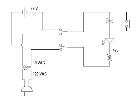
On Project no.14 - Blocking Direct Current the schematics is this

enter image description here

and it is also clearly stated on the Step that the capacitor is polarized

enter image description here

I understand the concept of the project, to show that capacitor block DC and allow AC current. but the question is why did he use polarized on an AC circuit?

\$\endgroup\$
1
  • \$\begingroup\$ The diode makes it such that the AC source (when switched in) only conducts in one direction. \$\endgroup\$
    – Ste Kulov
    Commented May 31 at 2:10

1 Answer 1

0
\$\begingroup\$

The truth is, the capacitor doesn't have to be polarized. However, if you are using a polarized capacitor, it has to put in the circuit the way it is shown as to not charge the capacitor backwards (reverse bias). Electrolytics will fail, sometimes catastrophically, when charged with the wrong polarity.

In your defense, this is a very poor circuit for learning and demonstrates bad design practices that I don't want to get into right now. But to give you the gist of what's irking me:

You don't want to slam a switch directly across a charged capacitor to discharge it. It should have some series resistance. At low voltage and low capacitance, and for learning purposes only, this could be acceptable (still poor design).

The LED is reverse-biased when the push switch is depressed and the circuit is operating off the transformer. This is not good for the LED. But at 9VAC, and for learning purposes only, this could be acceptable (again, still poor design).

This demonstration could have been done with a SPST switch instead of a DPDT switch. This is just me being picky. I assume the DPDT switch depicts greater "isolation" of the AC vs DC mode.

\$\endgroup\$
3
  • \$\begingroup\$ i understand the DC part of this schematic and i know from what i learned so far that this capacitor is not powering the LED when discharging because the LED is on reverse biased. my only concern is the AC part will it charge and discharge the capacitor when the current goes to the positive part since AC is alternating its polarity. \$\endgroup\$ Commented May 31 at 3:44
  • \$\begingroup\$ @MichaelPingol No. The AC will not discharge the capacitor. The only thing in the whole circuit that will discharge the capacitor is the push switch. That LED is a diode, and that's the only capacitor path when the switch is open. It will "block" the reverse AC voltage. AC is really just "DC in a moment of time". In other words, just consider the AC as 2 DC parts [in time]. You have +9DC for the first moment in time and you have -9V for the second moment. That's how you can evaluate the circuit - a DC circuit but consider both polarities. \$\endgroup\$
    – MOSFET
    Commented May 31 at 3:58
  • \$\begingroup\$ @MichaelPingol Another idea: think about putting the 9V battery where the transformer is instead. Evaluate the circuit. Now flip the battery. Re-evaluate the circuit with the new polarity. The AC analysis here really is just two DC evaluations. In fact, this is exactly the analysis for the case where the AC is a square wave. \$\endgroup\$
    – MOSFET
    Commented May 31 at 4:02

Your Answer

By clicking “Post Your Answer”, you agree to our terms of service and acknowledge you have read our privacy policy.

Not the answer you're looking for? Browse other questions tagged or ask your own question.