I'm struggling to understand the concept of "electric loading" or "current density" in a real motor.
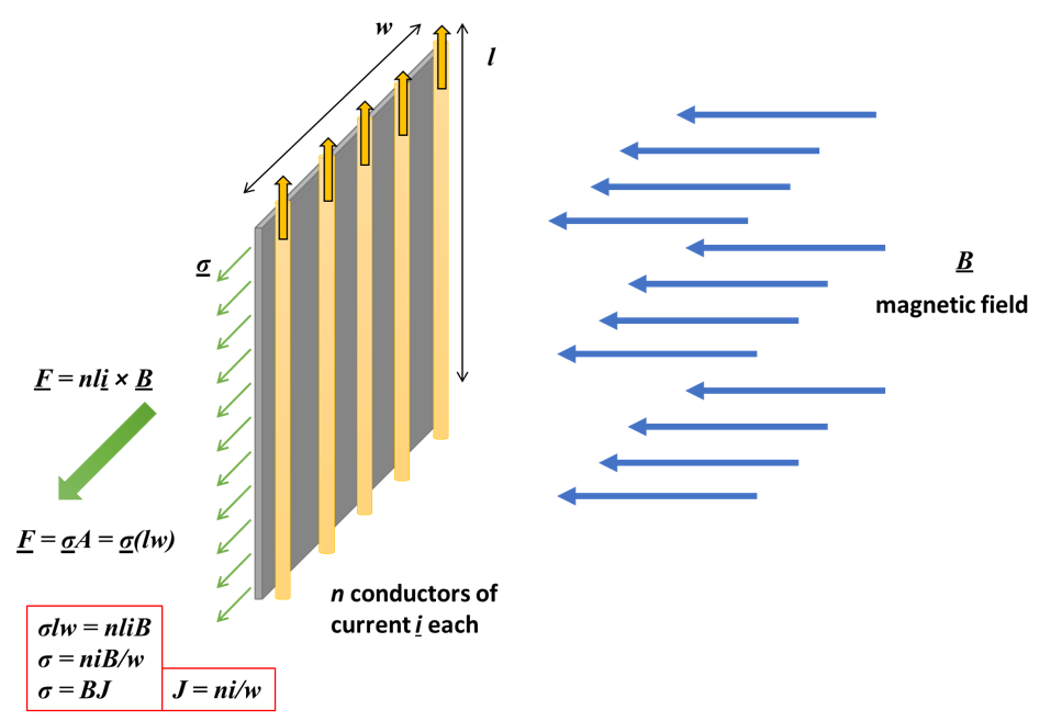
Soong explains how a sheet of conductors in a magnetic field generate force on that sheet which I've illustrated in Fig 1. You can re-arrange terms and define an "electric loading" factor (J in my illustration, A in Soong's paper) which has units Amps/Length. This is very clear to me.
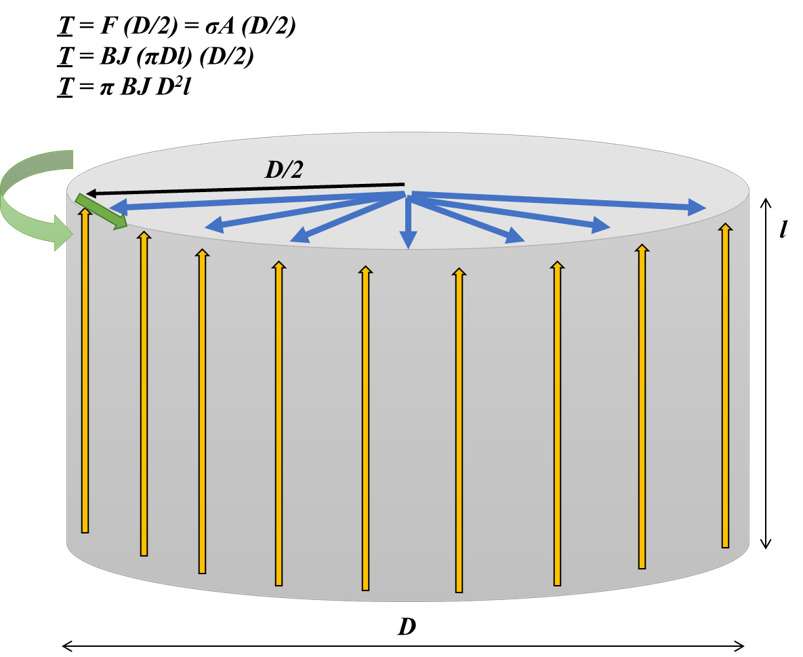
If you wrap the the sheet as a tube, you can model the torque generated by a motor. This time, the force has a moment-arm of the radius (D/2), and the field/wire are interacting along the lateral surface area of the tube, as illustrated in Fig 2. In this case, electric loading would be defined as J = total conductor current / circumference [Amps/Length]. Also very clear.
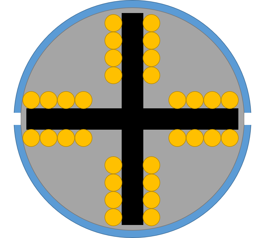
I don't understand how electric loading contributes to torque if you arrange the conductors around slots like in a real motor as illustrated top-down in Fig. 3. Then, it seems like only the conductors at edge of the slot are contributing to torque production. Therefore, the conductors inside are useless which I know is not true. How do you define electric loading in this arrangement?
Since each slot's conductors are all contributing to generate one slot's magnetic field, do you visualize all a slot's conductors as acting at the circumference and compute the current density as:
J = number of loops/slot * number of slots * current in each loop / circumference [Amps/length]
???

