1
\$\begingroup\$

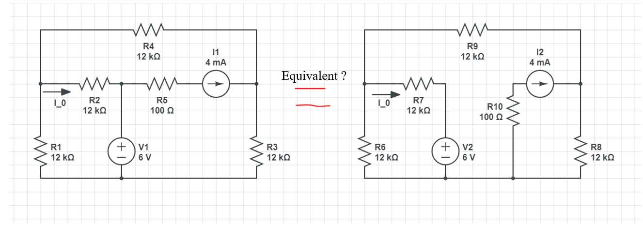
In this question, someone shows me that these two circuit are equivalent. I want to make sure that my idea about why is these two circuits are equivalent, is correct.

enter image description here

The inner resistor of an ideal current source is infinity,and how much current that current source provide to the circuit, how much will the circuit feedback to the current source, I mean if a current of \$x\$ A flows from the current source, then that \$x\$ A current will flow into the same current source, that is the reason why we can let the current source be attached to a ground.

So if I connected the resistor next to the current source, the equivalent circuit is as below:

enter image description here

Is my thinking right?

\$\endgroup\$
2
  • 1
    \$\begingroup\$ If you read the answers carefully you will see that the two circuits are not equivalent in general. The modification was only possible because you were looking for one specific current. \$\endgroup\$ Commented Apr 23, 2020 at 11:41
  • \$\begingroup\$ @ElliotAlderson correct! \$\endgroup\$
    – Andy aka
    Commented Apr 23, 2020 at 13:30

2 Answers 2

1
\$\begingroup\$

The inner resistor of an ideal current source is infinity,and how much current that current source provide to the circuit, how much will the circuit feedback to the current source, I mean if a current of \$x\$ A flows from the current source, then that \$x\$ A current will flow into the same current source, that is the reason why we can let the current source be attached to a ground.

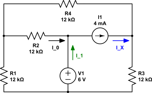
No. It is true that the same current that leaves the current source, has to enter it again. So, in the circuit below \$I_X=I_0+I_1 = x\$ A. But it is not the reason you can ground the current source. How would you know what value \$I_0\$ and \$I_1\$ have and conclude that you can simply connect the current source to ground?

schematic

simulate this circuit – Schematic created using CircuitLab

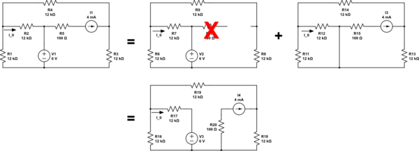
The reason you can ground the current source is because you can apply the superposition theorem:

The superposition theorem states that in a linear circuit with several sources, the current and voltage for any element in the circuit is the sum of the currents and voltages produced by each source acting independently.

So,

  • first take the contribution of the voltage source, zeroing out the current source, which implies it can be replaced by an open circuit. Note that in that partial circuit also the 100 Ω resistor can be removed.
  • then take the contribution of the curent source, zeroing out the voltage source, which implies it can be replaced by a short circuit.

schematic

simulate this circuit

\$\endgroup\$
7
  • \$\begingroup\$ @shineele Reading your original question, I afraid that if my answer is correct, your other question hasn't been answered... \$\endgroup\$
    – Huisman
    Commented Apr 23, 2020 at 7:17
  • \$\begingroup\$ Oh, I think it has!!! I didn't need to ground the current source; I grounded it to make it less of a stumbling block to the learning curve for @shineele. I could have said that it is dislocated entirely and, is "sourced from infinity" (poetic I know) and it just injects a current from somewhere unknown but, that would have raised eyebrows and slowed the learning curve. However, if I were at all interested in the current out of the voltage source then I still have to respect its position as attached to said voltage source. But, that wasn't what the question was. \$\endgroup\$
    – Andy aka
    Commented Apr 23, 2020 at 7:57
  • 1
    \$\begingroup\$ I'm starting to rethink how I teach superposition. 'Remove the voltage source and replace with a short' always sounds a bit drastic, and I wonder if some people baulk at it. 'Dial the voltage source down to 0 V' performs the same function. It may still need a 'of course, the voltage source has zero Rout, so now you might as well replace it with a short' so the schematic can be redrawn more tidily. Thoughts? \$\endgroup\$
    – Neil_UK
    Commented Apr 23, 2020 at 8:02
  • \$\begingroup\$ @Neil_UK I think you're right. Nihilating / zeroing out the contribution of the other sources would indeed be a better terms than disabling. Updated my answer. \$\endgroup\$
    – Huisman
    Commented Apr 23, 2020 at 9:00
  • \$\begingroup\$ @Huisman Yes, you've found a good, short, turn of phrase for it. \$\endgroup\$
    – Neil_UK
    Commented Apr 23, 2020 at 9:05
2
\$\begingroup\$

In this question, someone shows me that these two circuit are equivalent.

I didn't say that it was equivalent - I made a simplification that allowed me to find the current through R4 which then permits finding the current through R2. However, it can be made equivalent with one extra feature (splitting a current source): -

In your original question, you were interested in finding current \$I_0\$. So, my method was perfectly valid. However, if you were interested in knowing the current flowing from voltage source V1 then you would have to replicate the current source like this (I3 in the red box): -

enter image description here

The above would be the "true" equivalent circuit.

I3 (4 mA) is now correctly drawn from V1 but, it did not affect \$I_0\$ and so, in the original problem, I didn't bother to include it as you were only solving for \$I_0\$.

Regards your second question, if you were interested in the power dissipated in R10 then you have to keep it in series with the current source and, if the current source moves (to make analysis easier) then the added resistor moves too.

However, if you do introduce a new current source (as per above), you don't need to introduce a new extra resistor (a la R10) in series with current source I3 (placed across V1). There can only be one R10 even if you duplicate the current source. A resistor in series with a current source does not affect that current.

\$\endgroup\$
4
  • \$\begingroup\$ Can you please explain how you found the equivalent circuit to the original question and this one , actually i could not get it. your help will be appreciated \$\endgroup\$
    – hero
    Commented Apr 23, 2020 at 10:54
  • \$\begingroup\$ @hero you want me to explain how I can convert the single current source on the left-hand diagram into the two current sources on the right-hand diagram, yes? \$\endgroup\$
    – Andy aka
    Commented Apr 23, 2020 at 11:08
  • \$\begingroup\$ @hero OK, it's called source-splitting and is covered in this document. This document covers both current sources and voltage sources and how to split them. In general it's all about source transformation methods. \$\endgroup\$
    – Andy aka
    Commented Apr 23, 2020 at 13:22
  • \$\begingroup\$ splitting a current source video \$\endgroup\$
    – Andy aka
    Commented Apr 23, 2020 at 13:28

Your Answer

By clicking “Post Your Answer”, you agree to our terms of service and acknowledge you have read our privacy policy.

Not the answer you're looking for? Browse other questions tagged or ask your own question.