1
\$\begingroup\$

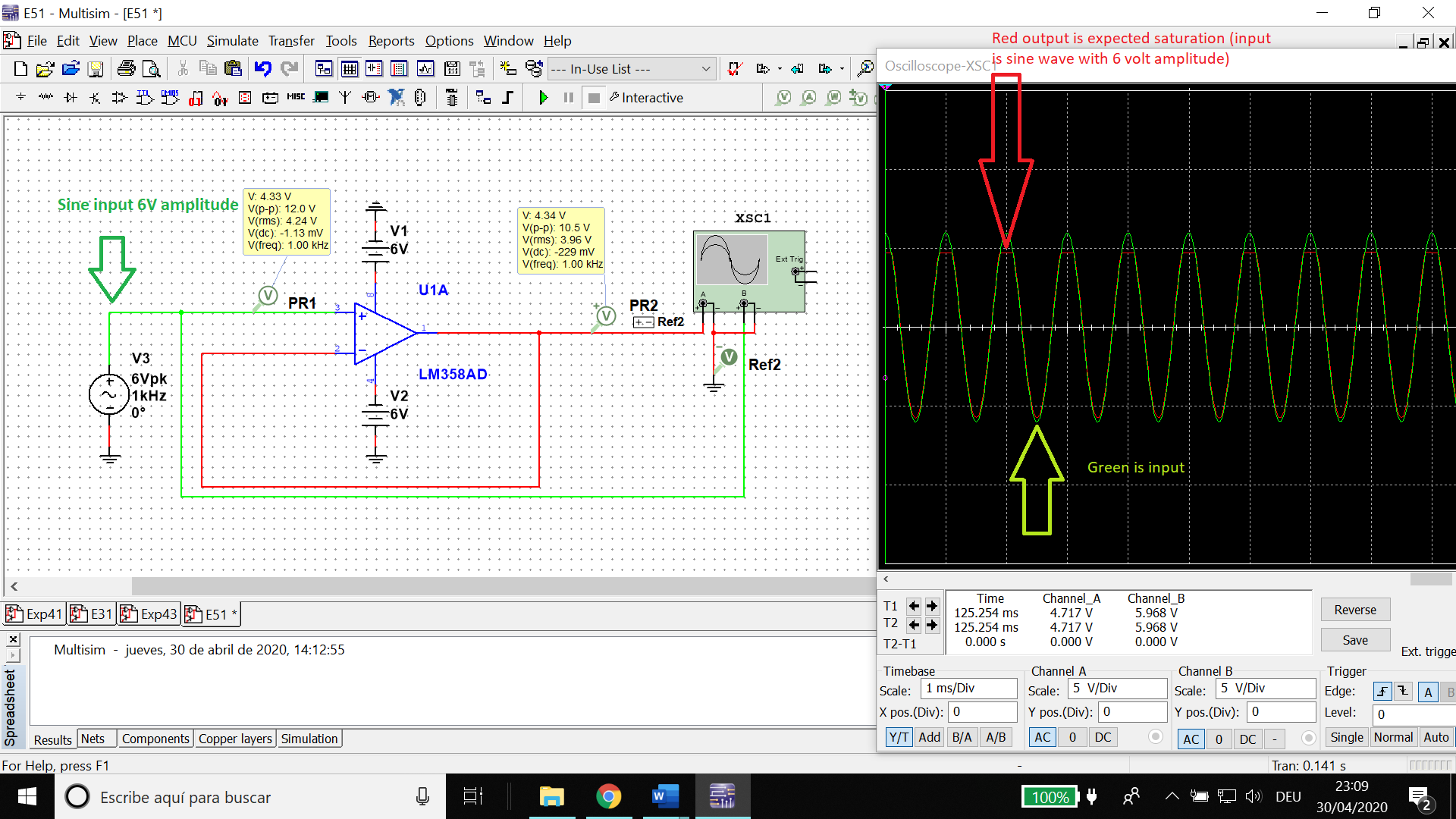
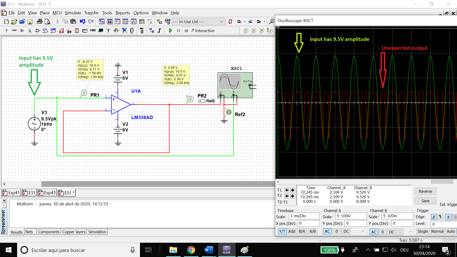
I have designed a buffer amplifier using an LM358 op-amp, with an input of a 1kHz sine wave and a power supply of +/-6V. whenever I increase the input sine amplitude above a certain threshold, I get a weird output (unlike the normal saturation that we all expect such as the one in Figure 1).

Expected behaviour for saturation

Figure 1 (Above). Normal saturation.

Unexpected behaviour for saturation

Figure 2 (Above). Weird unexpected saturation.

Why is the saturation in Figure 2 like that? I am used to Figure 1's output but not Figure 2. I guess it's linked to the -+ 6 Volt supply, but I'm really lost.

I've tried looking online for similar waveforms, but I found nothing.

\$\endgroup\$

4 Answers 4

1
\$\begingroup\$

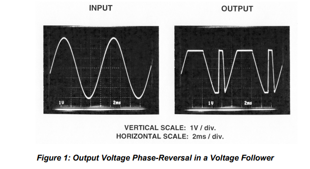
The "weird" output looks like "phase reversal", which can occur in some op amps when the input common mode range is exceeded:

enter image description here

Source: https://www.analog.com/media/en/training-seminars/tutorials/MT-036.pdf

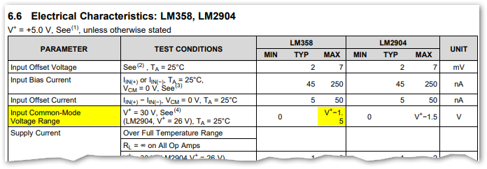
The TI datasheet for the LM358 indicates that the input common mode range has a maximum of 1.5V below the positive power supply voltage, i.e. 4.5V in your case. As pointed out in this thread on TI's E2E forum, the LM358 is susceptible to phase reversal.

The LM358 model in your simulation is evidently accurate enough to model this phase reversal behavior, but in general you need to keep your op amp within its specified limits (input common mode range here) in order for the simulation to reliably model reality (and you need to keep a real op amp within its specified limits anyway).

\$\endgroup\$
2
  • \$\begingroup\$ Strange because LM358 from ST dos not shown any sign of "phase reversal" with comparison, for example, TL072 electronics.stackexchange.com/questions/432775/… But maybe because my CM voltage did not exceed the VCC supply value. \$\endgroup\$
    – G36
    Commented May 1, 2020 at 6:12
  • \$\begingroup\$ @G36 Yeah, the OP's simulations suggest that phase reversal only occurs when the input exceeds the supply voltage. \$\endgroup\$
    – Null
    Commented May 1, 2020 at 13:35
2
\$\begingroup\$

You exceed the normal operating input common mode range for the chip.

If you exceed that, it can't operate normally any more.

It is also impossible to say how accurate the simulator is.

\$\endgroup\$
0
\$\begingroup\$

enter image description here

Figure 1. Input common-mode maximum voltage. From TI LM358 datasheet.

  • The datasheet says that maximum input voltage is V+ - 1.5 V.
  • Your V+ is 6 V so maximum input voltage should be 4.5 V.
  • You are giving it peaks of 9 V.

Since you have exceeded the datasheet ratings the chip will not operate as intended and is no longer an op-amp. You will reverse bias the inputs, they may breakdown and cause the chip to latch up. The simulator might survive. The chip may not.

\$\endgroup\$
1
  • \$\begingroup\$ The chip will survive, the inputs can go much above the V+ supply. It just can't provide a sane output. \$\endgroup\$
    – Justme
    Commented Apr 30, 2020 at 21:47
0
\$\begingroup\$

The data sheet specifies the common mode input range as Vcc-1.7V, which would be 4.3 volts in your case.

Note that in an inverting configuration, the amp would see a virtual ground as the input, so you'd be OK, but you'd still have output saturation.

\$\endgroup\$

Your Answer

By clicking “Post Your Answer”, you agree to our terms of service and acknowledge you have read our privacy policy.

Not the answer you're looking for? Browse other questions tagged or ask your own question.