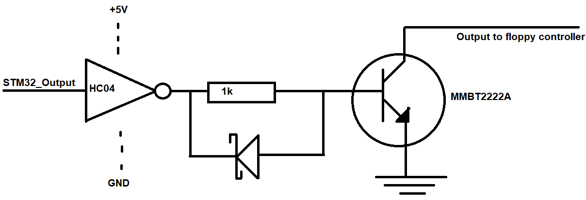
In a design for the popular "gotek" floppy drive emulator, as per the standard, the outputs from the floppy emulator are open-collector.
An STM32 is used as the processor. This drives a 74HC04, which then drives MMBT2222A NPN transistors through a 1k resistor as the open-collector outputs.
On just one of these six drivers (the serial DATA_OUT from the floppy emulator), there is a schottky diode across the base resistor. What is the purpose of it?
My guess is that it causes the transistor's base capacitance to discharge quicker when the HC04 goes LOW, so this driver will switch off quicker than the others? (I'd think this level of timing precision wouldn't be needed for floppy drives).
On a side-note: I am developing an enhanced version for vintage computers (original is very basic without modifications). I am trying to optimize the design. Based on looking at what other floppy drives use to drive the open-collector outputs (often a 7438), I should be able to use a 74LVC07, or a 74HC07 with 3.3V powering it, and do away with the transistors? Or am I missing something important. Or the safe option: use the original design (but use HCT04 instead).
A 5.25" floppy drive on the same open-collector "bus" can have 150-ohm pull-ups. This would cause significant current that would be pushing a logic IC, so I wonder why floppy drives get away with using 7438 as the driver.

