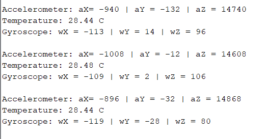
I don't know this specific part, but you don't need to know how the axis are physically oriented, because your device will never be mounted with 100% accuracy in ideal conditions. This is gonna be some evil little QFN fine-pitch MEMS, so the SMD process alone will give quite some inaccuracy in position, not to mention the inaccuracy that comes with how the final PCB is mounted.
So you'll need some means to calibrate the accelerometer when it is sitting still at 1G. A serial bus command, a button, a jumper etc. The (x,y,z) offset you get then, is the 1G vector pointing towards the centre of the earth. All your calculations from there on must be based on this offset.
As for why you have different values from time to time, there could be many explanations. This part apparently uses internal ADC to read the data, for example the datasheet mentions 16 bit ADCs. That's quite some resolution - with 3.3V supply, one ADC unit would be 3.3/(2^16) = 50.35uV. Fluctuations in ref voltage will mean ADC noice. And then ADC are by their nature giving unstable output. So I suspect this is the natural state of things - a moving average filter in software can usually handle it.
Though you should investigate how the part's supply and ref voltages look. Any noise from switch regulators or line etc will affect the part. PCB layout and decoupling caps will of course matter too. And yet another culprit could be rounding math or floating point inaccuracy in software.

