0
\$\begingroup\$

I have 3.3V micro and +/- 12V square wave input I need to measure.

As my MCU can only read 0 to 3.3V, I would like to ask the best way to "translate" this +/-12V signal into 0 to 3.3V.

I try to read but there are many many solutions and I can't figure out which is better to do.

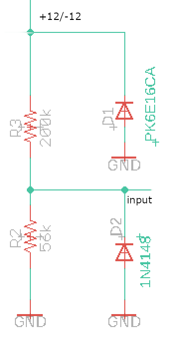
I'm adding my actual schematics:

Signal is a PWM @ 1000Hz coming from EV car. I can read 0-12V to 2.625 V maximum in input.

enter image description here

\$\endgroup\$
4
  • \$\begingroup\$ Where does the +/-12V come from (can you load it with some resistance) and is +/-12V the maximum it will ever reach? \$\endgroup\$ Commented Jun 10, 2020 at 5:48
  • \$\begingroup\$ I added my actual schematics, unfortunately can't read negative voltage with that \$\endgroup\$
    – mapomapo
    Commented Jun 10, 2020 at 5:54
  • \$\begingroup\$ yes +/-12 is the maximum \$\endgroup\$
    – mapomapo
    Commented Jun 10, 2020 at 5:59
  • 1
    \$\begingroup\$ Also see here. \$\endgroup\$
    – jonk
    Commented Jun 10, 2020 at 7:22

2 Answers 2

3
\$\begingroup\$

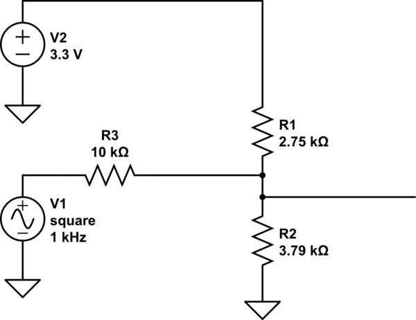
Eg.

Consider the input at -12V we can write 3.3/R1 = 12/R3
Consider the input at +12V we can write 3.3/R2 = (12-3.3)/R3
Pick R3 to be something in a good range, say 10K

Then the results fall out as below.

If you want to allow for a bit more such as +/-14V, just substitute the values, and you can scale the three resistors as desired up to the maximum your ADC likes to see at the input, or the minimum your loading permits.

schematic

simulate this circuit – Schematic created using CircuitLab

\$\endgroup\$
5
  • \$\begingroup\$ You're my new HERO!!! :) at this point I would need to remove diode too ? \$\endgroup\$
    – mapomapo
    Commented Jun 10, 2020 at 6:40
  • 1
    \$\begingroup\$ You can leave D2. D1 looks like it should have died already if -12 is relative to ground. \$\endgroup\$ Commented Jun 10, 2020 at 6:46
  • \$\begingroup\$ yep I'm actually still design. for final consideration which will be the range on output ? at 12V = 3.3v and -12V ? sorry maybe stupid question but I'm really novice \$\endgroup\$
    – mapomapo
    Commented Jun 10, 2020 at 6:49
  • 1
    \$\begingroup\$ thanks, I re read and understand the calculation ( most important things) I'm going with 28/38K and 110K on the 12v , this results into a 3.191 maximum voltage that it's more safe than exactly 3.3v on the mcu input . THANKS!!!! \$\endgroup\$
    – mapomapo
    Commented Jun 10, 2020 at 7:10
  • \$\begingroup\$ @mapomapo - Please remember to come back and accept (green "tick") the best answer (this one, or an even better one, if a better one is posted) to indicate that your problem is solved. See: "What should I do when someone answers my question?" Thanks. \$\endgroup\$
    – SamGibson
    Commented Jun 10, 2020 at 12:40
0
\$\begingroup\$

You can keep D2 and connect (an)other diode between the input and 3.3 V (with its cathode connected to 3.3 V power supply).

And, of course, insert a resistor between the input source and the "micro" input (if the input source does not have any internal resistance, i.e., it is a perfect voltage source).

The name of this circuit is "double diode limiter".

\$\endgroup\$

Your Answer

By clicking “Post Your Answer”, you agree to our terms of service and acknowledge you have read our privacy policy.

Not the answer you're looking for? Browse other questions tagged or ask your own question.