From a general perspective, to do these checks you need to locate the hardware specifications for the programmer you are using. This information is usually available from the manufacturer in the form of a specifications page or a datasheet. If no such page exists, either contact the manufacturer directly, or don't buy it (same goes for any electronic component!).
You can the find the corresponding data for the microcontroller itself in the datasheet available from chip manufacturer (in your case NXP). The IC datasheet will again tell you the IO voltage for the microcontroller.
Beware that the numbers for both programmer and MCU may be stated in terms of %age of VDD or VDDIO or some such similar. This means you will need to know what voltage your microcontroller is running at, and additionally how the voltage of the programmer is set.
A further point to node is that many, but by no means all, programmers have a target voltage reference pin which is an input to the programmer that you drive from the supply voltage of the target in order to allow the programmer to level shift its signals to match the target. This pin if present must be connected otherwise comms will fail.
Once you know the specifications for both in terms of a voltage level, you simply then need to compare the numbers and ensure that \$V_{OH} \ge V_{IH}\$ and \$V_{OL} \le V_{IL}\$ in both directions (MCU->Programmer and Programmer->MCU) to make sure the programmer and target can talk to each other.
As a final note, some microcontrollers with built in flash memory may support running and communication at lower VDD voltages, but are unable to be programmed below a certain level (certain ATTiny MCUs do this for example), so make sure that your target is running at a voltage at which it supports programming.
On to your specific case. You haven't specified in the question which specific model of J-Link you are using. Furthermore the manual you have linked to is a user guide, not the specifications of the programming adapter.
Looking on the manufacturers website, we can see there is a comparison table of all of the different J-Link programmers, which shows the key specs of each of the models. The following is an extract from the table where we can see the supported target voltage ranges of each.

From this table we can see that all of the except for the J-Link EDU Mini support any voltage within the range of 1.2V to 5V. The voltage of this interface is set by connecting the supply voltage of the target to the reference voltage pin on the 20-way interface.
Further details are then available on the detailed specification pages of each of the individual programmers - clicking on one of the programmer names in the title row of the table linked above takes you to the page for that programmer.
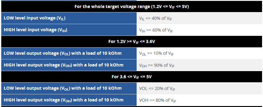
For example, if I click on the first programmer in that table, we get the full specs of the programmer with relation to the input voltage specifications. The following is the voltage specifications for the J-Link EDU programmer:


