0
\$\begingroup\$

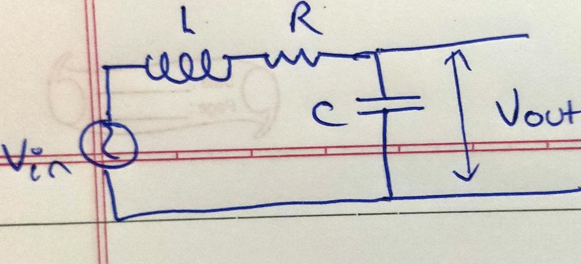
I have this AC voltage divider here wish I want to find the exit voltage of. What I've done is I've applied the voltage divider formula:

$$ V_{out} = \frac{Z_2}{Z_1 + Z_2} V_{in}$$

Now that I have got the magnitude of \$ V_{out} \$, I am trying to figure out the sinusoidal function associated with it. But I'm not exactly sure how to do it

Diagram of this scenario:

enter image description here

$$ Z_{R-L} = \sqrt{ R^2 + w^2 L^2}$$

$$ Z_{C} = \frac{1}{wC}$$

hence,

$$ V_{out} = \frac{ V_{in}}{ 1+ wC \sqrt{R^2 + w^2 L^2} } $$

assume \$V_{in}\$ to be some generic sinusoidal function like \$ V_{in} = A sin( \omega t)\$

\$\endgroup\$
9
  • \$\begingroup\$ Can you show us your complex expression for the voltage divider? \$\endgroup\$ Commented Jul 15, 2020 at 22:33
  • \$\begingroup\$ How do you mean ? you mean with the values? \$\endgroup\$
    – Brian
    Commented Jul 15, 2020 at 22:33
  • 2
    \$\begingroup\$ To get the phase you're going to have to invite Mr. "j" to the party (j = \$\sqrt{-1}\$). \$\endgroup\$ Commented Jul 15, 2020 at 22:43
  • 2
    \$\begingroup\$ Electrical engineers usually use j rather than i, because we prefer to reserve i for current. \$\endgroup\$ Commented Jul 15, 2020 at 22:49
  • 5
    \$\begingroup\$ @HelenaWells I is used for DC current and i(t) for varying or i for small-signal current. \$\endgroup\$ Commented Jul 15, 2020 at 23:10

3 Answers 3

1
\$\begingroup\$

The question's values for impedances \$Z_{R-L}\$ and \$Z_C\$ are actually the magnitude of those impedances. I suspect that the approach was mixing time-domain and frequency-domain approaches; I will address both to make the distinction.

Since the inductor voltage depends on changing current and the capacitor current depends on changing voltage, a time domain analysis produces a differential equation.

$$ v_{OUT}(t) = v_C(t) = v_{IN}(t) - L\frac{d}{dt}i_{IN}(t) - Ri_{IN}(t) $$

and since the input current is split between the capacitor and output: $$ i_{IN}(t) = C\frac{d}{dt}v_{OUT}(t) + i_{OUT}(t) $$ putting them together: $$ \begin{align} v_{OUT}(t) &= v_{IN}(t) - L\frac{d}{dt}\big(C\frac{d}{dt}v_{OUT}(t) + i_{OUT}(t)\big) - R\big(C\frac{d}{dt}v_{OUT}(t) + i_{OUT}(t)\big) \\ &= v_{IN}(t) - LC\frac{d^2}{dt^2}v_{OUT}(t) - L\frac{d}{dt}i_{OUT}(t) - RC\frac{d}{dt}v_{OUT}(t) - Ri_{OUT}(t) \\ \end{align}$$

This is still somewhat manageable, except that \$i_{OUT}\$ likely also depends on \$v_{OUT}\$. Flipping to the frequency domain, the diff-eq turns to algebra and we get a much better handle on the output load.

Let's show the output load explicitly, with an impedance of \$Z_{LOAD}\$. Also note that L and C have impedances \$j\omega L\$ and \$\frac{1}{j\omega C}\$, respectively. See this concise reference for more detail there. $$ $$ schematic
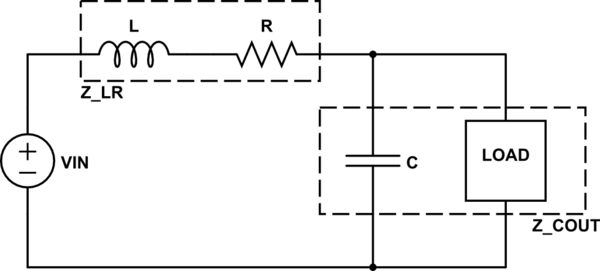
Preserving our output nets, we can lump together L with R (in series) and C with the load (parallel). This gives:

$$ \begin{align} Z_{LR} &= j\omega L + R \\ Z_{COUT} &= \bigg({\frac{1}{j\omega C}}^{-1}+{Z_{LOAD}}^{-1}\bigg)^{-1} \\ &= \frac{Z_{LOAD}}{j\omega C Z_{LOAD}+1} \end{align}$$

Now you can use the resistor divider rule to calculate a transfer function: $$ H = \frac{V_{OUT}}{V_{IN}} = \frac{Z_{COUT}}{Z_{LR}+Z_{COUT}} $$

And finally, the phase shift can be determined by comparing the real and imaginary parts of the transfer function: $$ \Theta = tan^{-1}\biggl(\frac{\mathfrak{Im}(H)}{\mathfrak{Re}(H)}\biggr)$$

\$\endgroup\$
8
  • \$\begingroup\$ Can you explain what is time and frequency domain? And shuldn't it be arctangent at the end? \$\endgroup\$
    – Brian
    Commented Jul 17, 2020 at 22:02
  • \$\begingroup\$ Oh, you are right! I will fix that right away and will try find a good reference for time/frequency domains. \$\endgroup\$
    – mbedded
    Commented Jul 18, 2020 at 1:07
  • \$\begingroup\$ I think a good way to understand time domain and frequency domain may be to look at the Fourier Transform from one to the other. \$\endgroup\$
    – mbedded
    Commented Jul 18, 2020 at 5:07
  • \$\begingroup\$ some people say fourier and some tell me laplace... what is difference? \$\endgroup\$
    – Brian
    Commented Jul 18, 2020 at 8:55
  • \$\begingroup\$ I still don't understand time vs frequency domain.. \$\endgroup\$
    – Brian
    Commented Jul 18, 2020 at 8:58
1
\$\begingroup\$

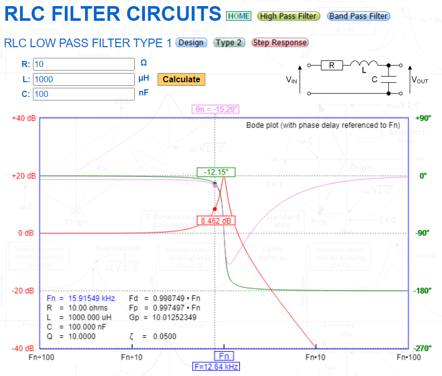
If you need to know real values and want to examine different scenarios then use an on-line calculator to give the frequency response of this: -

enter image description here

Here's an example: -

enter image description here

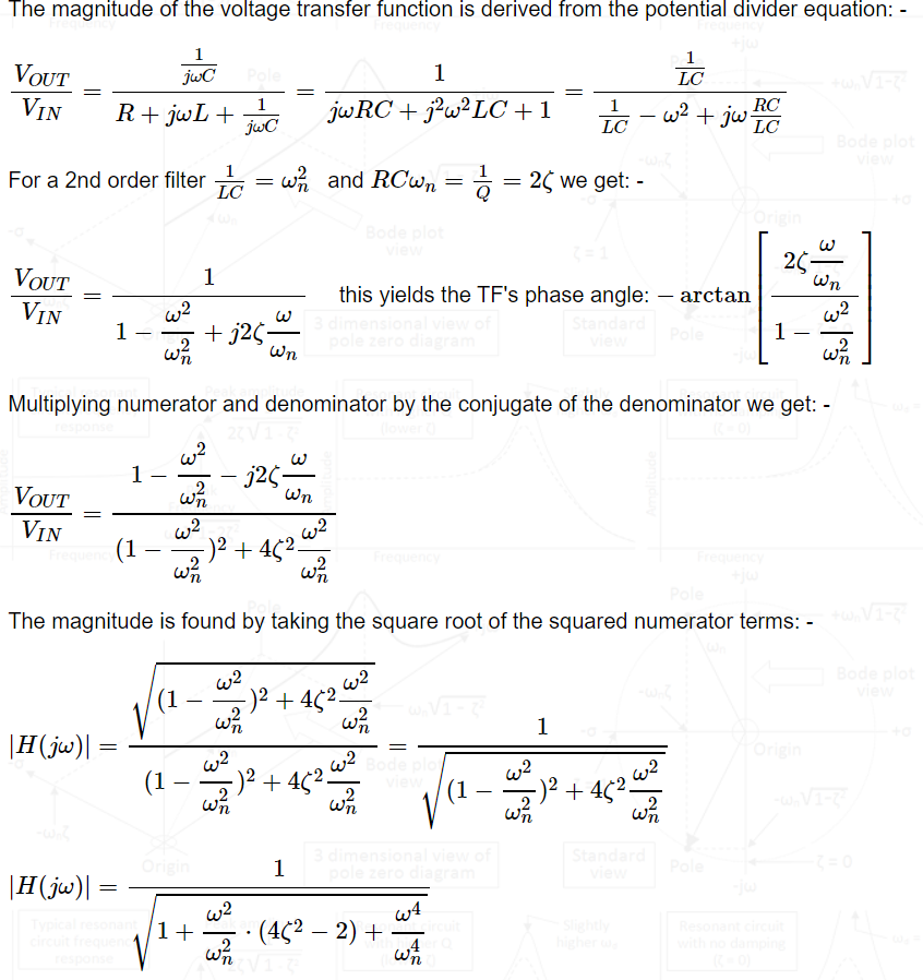
You also get the formulas and derivation: -

enter image description here

\$\endgroup\$
4
  • \$\begingroup\$ 1. What is a filter 2. why did you define 1/Q = 2 epislon thing? ( i dont knwo what symbol is called) \$\endgroup\$
    – Brian
    Commented Jul 18, 2020 at 13:20
  • \$\begingroup\$ The RLC circuit is a filter. It's a low pass filter, 2nd order type. the squiggly line is zeta, damping factor. Q is filter quality factor. \$\endgroup\$
    – Andy aka
    Commented Jul 18, 2020 at 15:41
  • \$\begingroup\$ can you explain these things in more detail? I haven't heard of these terms before like filter, damping factor. I've heard Q but , only basic understanding I have of it \$\endgroup\$
    – Brian
    Commented Jul 18, 2020 at 18:28
  • \$\begingroup\$ I think you might be out of your depth here. There is a whole term of coursework implied to understand this. \$\endgroup\$
    – Andy aka
    Commented Jul 18, 2020 at 18:31
-1
\$\begingroup\$

You cant just add voltages in AC because the voltage drop of the resistor is in a different phase with the voltage drop of the capacitor and is in a different phase with the voltage drop of the inductor.

In AC generally:

Current through a resistor has the same phase with the voltage drop of the resistor.

In capacitors current leads voltage by pi/2 rad.

In inductors voltage leads current by pi/2 rad.

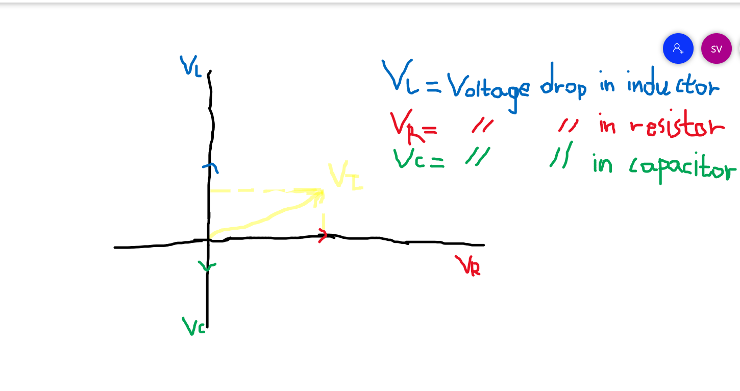
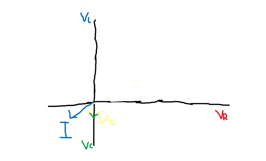
To find the total voltage drop you must draw this diagram:

enter image description here

The total voltage drop across all circuit elements will be sqrt(Vr^2+Vl^2+Vc^2).

To get the output voltage hide all the lines which represent the voltage drop of the resistor and the inductor:

Since we only have circuit elements connected in series the voltage will steal lead the current so the graph will look like that:

enter image description here

where I = Current.

I am a stubborn woman!

\$\endgroup\$
11
  • \$\begingroup\$ well problem is the circuit is branching out from the capacitor \$\endgroup\$
    – Brian
    Commented Jul 15, 2020 at 22:47
  • \$\begingroup\$ so, I don't think I can really add it like that \$\endgroup\$
    – Brian
    Commented Jul 15, 2020 at 22:48
  • \$\begingroup\$ Just made a random circuit to show the OP how it is done. \$\endgroup\$ Commented Jul 15, 2020 at 22:48
  • \$\begingroup\$ I'm op, and I'd like advice more in context with this problem / how to fix my approach \$\endgroup\$
    – Brian
    Commented Jul 15, 2020 at 22:49
  • \$\begingroup\$ I don't think everything is in series \$\endgroup\$
    – Brian
    Commented Jul 15, 2020 at 23:21

Your Answer

By clicking “Post Your Answer”, you agree to our terms of service and acknowledge you have read our privacy policy.

Not the answer you're looking for? Browse other questions tagged or ask your own question.