0
\$\begingroup\$

I must preface this with I am not an electrician. Just a hobbyist. I have a unique problem I am trying to solve. With the Covid situation our curling club needs a solution for their double takeout board. Currently its a sandwich board that is passed from sheet to sheet when someone completes a double takeout.

My idea is to have a foot switch at the end of every sheet that would control either a light above that sheet, or a scoreboard(type device) that would display the sheet that has last pressed the foot switch. The catch is only one switch will have priority and remove the light/scoreboard from the other sheets. ie. only one light can be illuminated or one sheet indicated on the scoreboard.

I started mocking this up at home with wall switches and soon realized the amount of wire there would be running back and forth.

Is there a pre-existing solution or a diagram of how to accomplish something like this that someone could point me to?

\$\endgroup\$
3
  • 1
    \$\begingroup\$ please do not use curling jargon in your description ... it makes the description unclear \$\endgroup\$
    – jsotola
    Commented Jul 19, 2020 at 6:30
  • 1
    \$\begingroup\$ What is a sheet thing that you talk about? Is it a curling lane? I have no-idea what a double takeout board is or a sandwich board? \$\endgroup\$
    – Andy aka
    Commented Jul 19, 2020 at 8:12
  • 1
    \$\begingroup\$ Diagrams would really help... \$\endgroup\$ Commented Jul 19, 2020 at 9:39

1 Answer 1

1
\$\begingroup\$

I get the sense that you want a thing with N buttons spread over a wide area the buttons each light a lamp and extinguish all other lamps when activated

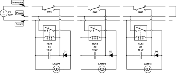
Here is my solution power (12v) is applied at one end and 3 wires connect between each adjacent pair of modules I've called the wires "interuptor" "power" and "return" that last module connects to a stub plug

Each module consists of a SPDT industrial pushbutton, a 12V relay a diode and a capacitor and the lamp enclosed in a suitable case, the lamp could be external to the case.

schematic

simulate this circuit – Schematic created using CircuitLab

when a button is activated it interrupts the current flow on the interuptor line shutting off power to the "power" line causing all the other relay to reset, in also diverts power to this relay causing it to set. and charging the capacitor, when the button is released current is resored to the power line and current flows through the relay contacts lighting the lamp and through the diode powering the relay.

the purpose of the capacitor is to maintain current to the relay while the switch is changing between its two states. if use find a switch with make-before-break then the capacitor is not needed and the diode can be replaced with a wire.

for the interconnects something like XLR connectors could be used they are rugged and have three terminals.

\$\endgroup\$
2
  • \$\begingroup\$ thank you this is exactly the solution for me. I was trying to do it with AC, however that is completely unneeded as LED's will probably be the lamps anyways. I figured relays would come into play and had originally tried to diagram that, but was not working because I didn't think about a capacitor. Didn't know about a make before break option either so I may look into that. Very easy solution and I can even make the scoreboard option with this, by having the switches be external and all the final connections made in an enclosed solution. Thanks again. \$\endgroup\$ Commented Jul 19, 2020 at 18:58
  • \$\begingroup\$ ac relays are slow, probably slow enough to work without the diode and capacitor. \$\endgroup\$ Commented Jul 19, 2020 at 23:59

Your Answer

By clicking “Post Your Answer”, you agree to our terms of service and acknowledge you have read our privacy policy.

Not the answer you're looking for? Browse other questions tagged or ask your own question.