1
\$\begingroup\$

I have to determine the capacitance of 2 conducting plate (fringe fields are ignored) with a certain area (5m^2 here) with a gap separating them (4mm here). The second plate is inclined at an angle of 45 degrees. The dielectric between the plates has Epsilon_r = 1.5

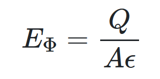
Now I have found a solution online by applying the boundary problem, and the result is 444pF. However, in my major we don't cover differential equations so we have to solve this problem using the "Gauss' method" by assuming one plate has a charge Q while the other has a charge -Q then getting the electric field and the voltage. From there we can get the capacitance by C = Q/Venter image description here
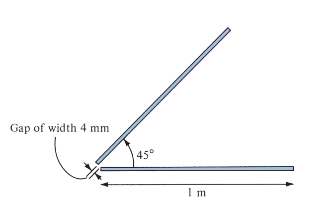
Now, if we ignore the fringe field the electric field would only by in the direction of the angle Phi (assuming cylindrical coordinates are used).

enter image description here

However that doesn't achieve the final results after getting the voltage. What's wrong here? What's the correct procedure to solve this problem?

Here is how the book list the way to solve these problems: enter image description here

\$\endgroup\$

3 Answers 3

0
\$\begingroup\$

Those steps described by the textbook apply mostly to situations where there is a lot of symmetry in the problem so that you can easily calculate the voltage between the conductors knowing only the total charge on the conductors. You will have to be more creative than following the recipe described in the text.

The charge distribution on these conductors will be very strongly nonuniform, with most of the charge accumulating closer to where the conductors almost meet. Most of the contribution to the capacitance will come from these regions, where you could make a decent assumption that the electric field lines run along lines of constant \$\rho\$.

For this problem, I would suggest you start by assuming a known voltage difference V between the plates. You need two key insights to solve this problem:

  1. You can approximate the E-field as being constant magnitude along lines of constant \$\rho\$, but as a function of \$\rho\$. This is an 'ignore the fringe field' approximation.
  2. You can find the surface charge density at a distance \$\rho\$ based on the electric field at a distance \$\rho\$. Hopefully you have done this before in a separate problem (hint- infinitesimal Gaussian pillbox near the surface of the conductor)

From that you will perform an integration like Dave Tweed is describing to get the total charge on each plate, which will depend on V. I think you know the rest.

\$\endgroup\$
9
  • \$\begingroup\$ Sadly, electromagnetism for computer engineers is an abridged version of the one for electrical/electronic engineers. For example, we are required to obtain it only using that method (exactly like the steps), so we have to assume +Q and -Q charges on both plates then get electric field, voltage, and finally capacitance. This exact question is in Sadiku's book and is solved using Laplace's (BVP): i.imgur.com/znPaTUu.png I know I'm asking a lot but it's because I spent an unhealthy amount of time on this problem trying to solve it so please bear with me! \$\endgroup\$
    – Big Papa
    Commented Jul 28, 2020 at 15:57
  • \$\begingroup\$ For reference, the last results I got (which is wrong) is C = (Epsilon * width)/(Phi * p) However, the correct answer is actually: C = (Epsilon * width * ln(L/d))/(Phi) So if I somehow integrate over row I actually get the correct capacitance (that cannot be a coincidence) \$\endgroup\$
    – Big Papa
    Commented Jul 28, 2020 at 16:01
  • \$\begingroup\$ You made progress. Notice that your expression for C depends on \$\rho\$? That cannot be. You are sort of pretending the E-field is uniform, when it strongly depends upon \$\rho\$. It is sort of like you calculated the contribution to the capacitance for a tiny element of width \$d\rho\$ and now you need to integrate over \$\rho\$ \$\endgroup\$
    – rpm2718
    Commented Jul 28, 2020 at 16:10
  • \$\begingroup\$ Thank you, that actually makes a lot of sense. But can I get there mathematically? Since if I follow along the steps rho is introduced when integrating over the line integral to get V (the differential element of Phi is rho * dPhi) I guess my question is: Where did I go wrong (mathematically)? Again thank you so much, honestly it feels like a veil has been lifted :)! \$\endgroup\$
    – Big Papa
    Commented Jul 28, 2020 at 16:23
  • \$\begingroup\$ Mathematically, it is like you are assuming a constant charge density calculated at some arbitrary value of \$\rho\$. To get there mathematically, you have to follow an approach such as the one I suggested, and focus on getting the charge density at a distance \$\rho\$, then integrating that charge density along \$\rho\$ to get the total charge Q.....then, C=Q/V \$\endgroup\$
    – rpm2718
    Commented Jul 28, 2020 at 16:31
1
\$\begingroup\$

What's wrong? The problem is that as the angle between the plates increases from zero, the E field and the charge distribution becomes nonuniform — a function of how far you are from the narrow gap. That's why the book is telling you to do the integration.

\$\endgroup\$
4
  • \$\begingroup\$ If you are talking about the potential then yes, I am aware. However if you substitute the value and do the integration (from Pi/4 to 0) then divide Q by the acquired V you would get 84.43pF (which is not correct). \$\endgroup\$
    – Big Papa
    Commented Jul 28, 2020 at 14:31
  • \$\begingroup\$ For reference here how it is solved using the BVP: i.imgur.com/znPaTUu.png In fact, I get the very same expression except of the ln (however I do have p in the denominator so perhaps some integral is missing) \$\endgroup\$
    – Big Papa
    Commented Jul 28, 2020 at 14:33
  • \$\begingroup\$ No, read step 3 again -- you need to integrate over L, not phi. E is now a non-constant function of L! \$\endgroup\$
    – Dave Tweed
    Commented Jul 28, 2020 at 14:34
  • \$\begingroup\$ But dl = dp a_p + p*dPhi a_Phi + dz a_z (cylindrical coordinates). and as established in the post above the electric field is only defined along Phi so it's only integrated along Phi (dot product) \$\endgroup\$
    – Big Papa
    Commented Jul 28, 2020 at 14:40
0
\$\begingroup\$

The charges distribute evenly on both conductors but the E field is inverse linear between parallel planes. But it is inverse quadratic between parallel lines where the fringe E-field may be strongest for large angles..

The surface area of the diverging planes is much greater than gap lines. The ratio of fringe capacitance to the total will greatly be dependant on the angle but may be analyzed as incremental parallel wires and added to the surface planes when the gap is small compared to the range between midpoints of each plane.

So I suggest you add several parallel wire capacitances for gaps equal to the plane thickness to the total. ie, 4mm, 5mm, 6mm gapped wire to estimate the fringe effects for 1mm thick plates.

Then integrate the inverse E-field strength for the two folded planes.

\$\endgroup\$

Your Answer

By clicking “Post Your Answer”, you agree to our terms of service and acknowledge you have read our privacy policy.

Not the answer you're looking for? Browse other questions tagged or ask your own question.