0
\$\begingroup\$

I am hoping to use a WeMos D1 Mini to control a Raspberry Pi. To save battery, I want to put the microcontroller into deep sleep and wake it up by pressing a button. The same button should be used to activate a method that will put the controller into deep sleep after shutting down the Raspberry Pi.

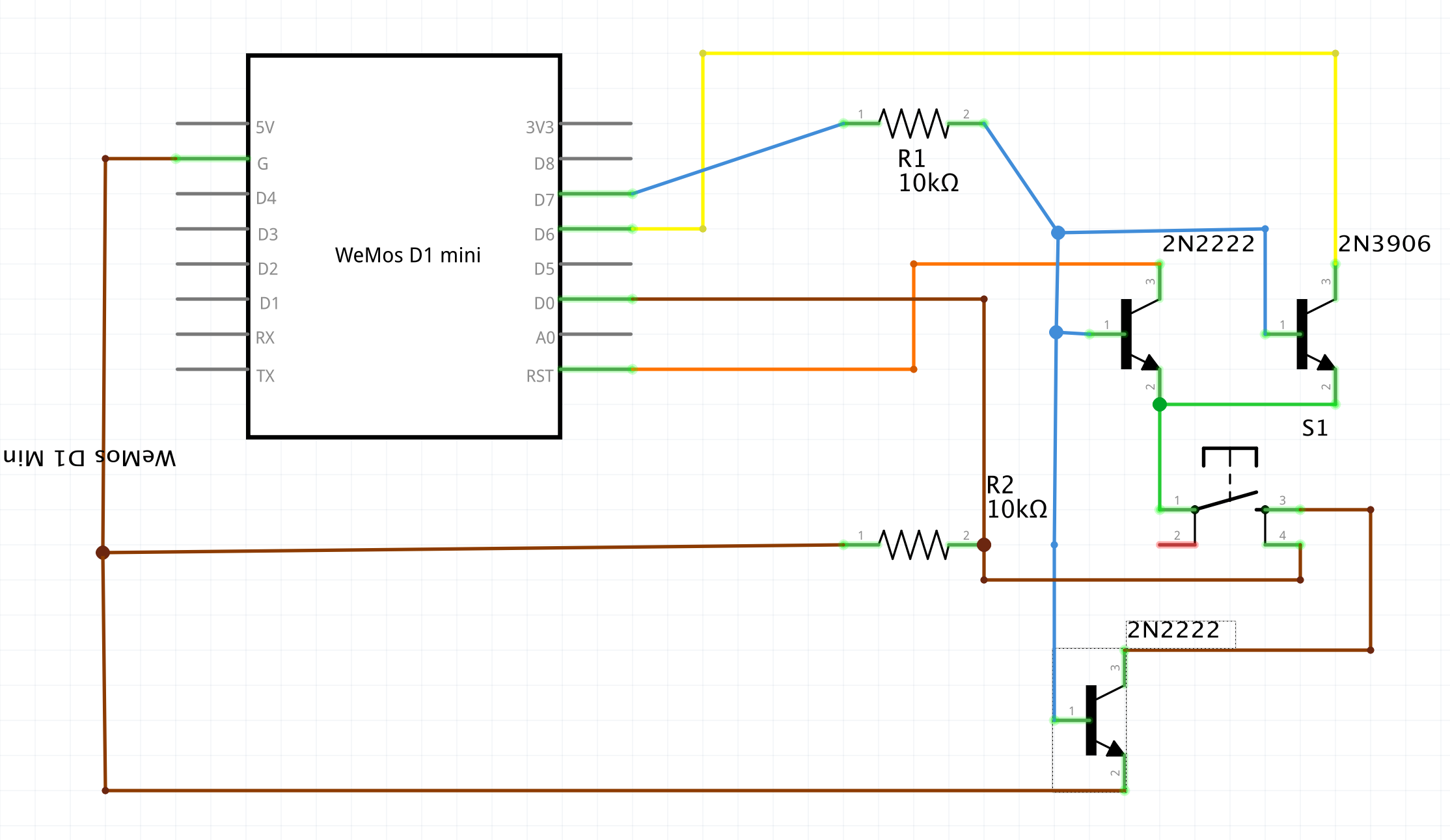
The thing is that the WeMos wakes up by shortly shorting the RST pin with GND. No problem with a push button. But when the microcontroller is awake, I don't want it to reset if the button is pressed - I rather want to detect the button press. So I am hoping to use two transistors, one NPN and another PNP, so that when I am waiting to wake up, the NPN allows the RST to connect to the button, where the other end is connected to ground via another NPN transistor enabled by the same base signal. When I want to detect a button press, the PNP will then allow the flow between the pins used for button reading.

So all transistors are using the same controller.

Except that it's not working. Last time my WeMos was even getting a bit hot, so I think I am shorting something.

Do I need diodes, for example between the button and the collectors of the two first transistors? Is there a better way to achieve this? (colours mean the wires do not touch)., f

enter image description here

\$\endgroup\$

1 Answer 1

1
\$\begingroup\$

At the very least, you're missing some parts. A transistor inverter needs a pull-up resistor on the collector (or a pull-down if it's a PNP), at the very least you're missing those. And it's difficult to do this sort of job with transistors in a way that is truly low power.

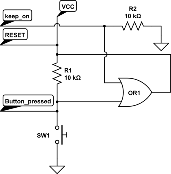
The way I'd do this is with an OR gate. If you can deal with surface-mount parts, use a 1-gate chip, otherwise use the lowest-power 74xx32 that fits your voltage level (74HC32 if 5V).

  • The "RESET" signal goes to your WeMos's reset line.
  • The "keep_on" line comes from your WeMos - I'm assuming that the WeMos chip will let this pin float when it's in reset. If it has an internal pull-up when it's reset, say so and we'll change the circuit. You'll need to configure this as an output, and set it to high, when you power on, and accept that you'll use some current in the resistor when its on.
  • The "button_pressed" line goes back to some input on the WeMos. Again, I'm assuming that the WeMos will let this line float when in reset. If there's an internal pulldown in reset, then that'll cause problems.

schematic

simulate this circuit – Schematic created using CircuitLab

\$\endgroup\$
4
  • \$\begingroup\$ Thanks @TimWescott! There's a pull down resistor on the collector, on the other side of the button. Would it help to add a pull up resistor for the collector on the npn? I really would prefer this design then using an OR gate since I don't have it with me right now. \$\endgroup\$ Commented Aug 16, 2020 at 7:56
  • \$\begingroup\$ Please edit your schematic so that it shows what you actually have!! How in the world can someone tell you what your stuff is doing if you don't accurately describe your stuff?!? \$\endgroup\$
    – TimWescott
    Commented Aug 16, 2020 at 14:35
  • \$\begingroup\$ Er... excuse me, but it is right there! See that there's a resistor between ground and the other side of the button, so when the button is pressed there's a connection between the collector and ground, with a resistor. It's right there. \$\endgroup\$ Commented Aug 17, 2020 at 16:44
  • \$\begingroup\$ Normally we indicate ground with a ground symbol, not a little 'G' on a chip. \$\endgroup\$
    – TimWescott
    Commented Aug 17, 2020 at 21:01

Your Answer

By clicking “Post Your Answer”, you agree to our terms of service and acknowledge you have read our privacy policy.

Not the answer you're looking for? Browse other questions tagged or ask your own question.