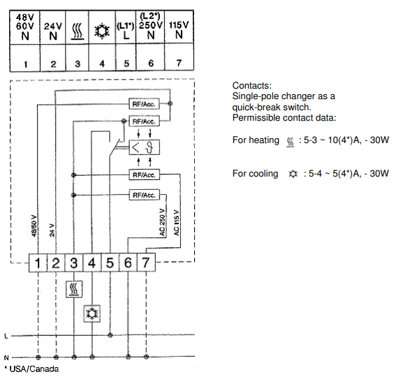
I think I get that 5 is L and can be connected to your heater (3) or cooling (4). So pins 3,4,5 are just a single pole double throw switch?
That is correct.
To understand the rest of the device I suspect that the significant clue in the technical description is -
Bi-metal controller as a temperature-sensitive element with thermal feedback.
Each of the RF/Acc. devices (Resistor feedback / accelerator?) acts as an internal heater to make the thermostat contacts change over from heating to cooling somewhat faster than would occur by changes in the cabinet temperature.
I saw a similar approach used in the thermostats used in carriage heating on electric trains many decades ago. In commissioning tests the original temperature control caused wild swings in temperature control and the carriages got too hot before the thermostat reacted and the bimetallic contacts opened. A small wirewound resistor was added inside the thermostat to heat it locally when the carriage heaters were on. This had the desired effect of opening the contacts much sooner and more frequently than would otherwise have happened and evened out the temperature surprisingly well.
The thermostat is designed to work on 24 V (standard industrial voltage), 48 / 60 V (telecoms), 115 V and 250 V systems. Notice that all of the RF/Acc. resistors are connected to 3 (heater live) and that you select which, if any, thermal feedback resistor you want to connect to neutral.
Depending on mounting location you may find that you don't need the feature. If you have a temperature probe or logger you can leave inside the cabinet you could establish this fairly quickly.
A quick web search throws up the following description for Patent US3940727A, Thermostat with automatic accelerator. This particular patent adapts the Rittal-style thermostat into a two-wire version by connecting the resistor in series with the contact and applying a pair of back-to-back diodes across the resistor so that the accelerator power is pretty much independent of the load resistance / impedance.
The invention relates to a thermostat, for instance of the bimetal type, with a set of switches, cutting the load in and out, and an accelerator resistor, thermally connected to the temperature-sensitive element of the thermostat.

Such accelerator resistors (thermal resistors) serve to speed up the heating of the temperature-sensitive element during the period when the switches of the thermostat have cut in a load, for instance a solenoid valve, for delivery of heating power to the room in which the thermostat controls the temperature. What is obtained by this is a cyclic functioning of the thermostat, which is cut out before the room has reached the desired temperature, with relatively short, constant cut-in periods and varying cut-out periods, depending on variations in the heating requirement.
Here an already known procedure is to connect the thermal resistor in parallel with the load (for instance the solenoid of a solenoid valve). Then the full operating voltage will be available to the accelerator resistor, and a constant heating power will be delivered to the thermostat.


