3
\$\begingroup\$

I'm working on a project to build a remote control app for some IR controlled toys like DeskPets, Robosapien, TOMY etc. including an IR transmitter that (hopefully) has a very high range.

I built an IR receiver that works with IrScrutinizer to capture the signals and export them to wave files.

I built 2 transmitters (one passive, one with a headphone amplifier powered over a USB port, later to be replaced with a LiPo battery). The LEDs are connected antiparallel to the left and the right channel. However these are not working reliably enough.

Both can send signals, however only if I play the recorded wave file using VLC media player and that only works a few times, leaving me wondering whether I broke the LEDs. A protoype app for Android successfully sent a signal once after countless attempts.

I have 2 theories:

  1. I forgot to set up specific settings in order to correctly play back wave files. Maybe VLC does something right when playing back a wave file. Playing back the captured signal directly via IrScrutinizer also works. I downloaded a soundboard app for Windows and playing back the same wave files didn't work.

  2. The wave files themselves are unreliable. While capturing the signals I noticed the timings are off (pauses are for example between 3395 microseconds and 3401 microseconds long). I didn't mess with the timings before exporting the wav files, but maybe if I fix the timings the signals could be read more reliably.

I hope you can help me fix this problem so I can continue with my project.

\$\endgroup\$
3
  • \$\begingroup\$ Can you confirm that the IR LEDs are working using your phone's camera? You might need to explain what exactly is meant by "* The LEDs are connected antiparallel to the left and the right channel.*" \$\endgroup\$
    – Transistor
    Commented Oct 4, 2020 at 9:07
  • \$\begingroup\$ One LED's plus pin is connected to the left channel and the other LED's plus pin is connected to the right channel. The minus pins are connected to the other respective channels. \$\endgroup\$ Commented Oct 4, 2020 at 9:15
  • \$\begingroup\$ You're going to need to provide meaningful detail of the circuit (especially your amplified version). Then synthesize a signal, send it, receive it with the same detection and compare. How are you accomplishing the 38 KHz carrier? Certain not through the phone audio path which can only manage the keying, and the receiver should reject anything without that, any tentative success is a lucky accident. \$\endgroup\$ Commented Oct 4, 2020 at 10:59

3 Answers 3

1
\$\begingroup\$

IR remote waveforms are not simply a coded sequence.

Rather they are a carrier such as 38 kHz which is switched on and off in the coded sequence.

Typically an IR receiver removes the carrier and outputs only the coding. Even if it did not, the carrier will not "fit" through a phone's audio path, but rather will be removed by the decimation filters in the ADC.

An IR sender requires a circuit to generate the carrier, the phone is only able to provide information used to key that carrier on and off, and maybe if harvested in various hacky ways, the electrically power.

You'll need to do some research yourself to find a suitable published circuit.

Any success without a proper carrier is a lucky accident.

\$\endgroup\$
4
  • \$\begingroup\$ I searched A LOT on Google. Most circuitries just take 2 LEDs, a headphone cable and just hook up the LEDs directly to the cable. Some of them hook the minus poles to the ground. And most of them say "Just download ZaZa Remote, set this setting and you're good to go" \$\endgroup\$ Commented Oct 4, 2020 at 11:31
  • 1
    \$\begingroup\$ Well, that shoulnd't work. We do engineering here, which means that we work with the known requirements of the task. You need to be keying a carrier, not blinking LEDs with an audio file. Until you are doing the things known to be needed, an expectation of success is unreasonable, and the only meaningful help that can be provided is to point out that fact. \$\endgroup\$ Commented Oct 4, 2020 at 11:46
  • \$\begingroup\$ Well, the superior help would be showing me a schematic i can use to make an IR sender that should work. And show me how to properly record the signals to later make the wave file with te keying information. I'd love to stick to my own guns with my software engineering skills, but unfortunately i need and i want to get my hands dirty and soldering circuit boards is way too much fun ;) \$\endgroup\$ Commented Oct 4, 2020 at 12:50
  • 1
    \$\begingroup\$ This site is not a design service; as explained in the answer you'll need to do your own research. We'll help you understand the problem, but we're not going to design the product/project for you. \$\endgroup\$ Commented Oct 4, 2020 at 21:43
1
\$\begingroup\$

As others have said, unless your audio output is capable of generating a carrier frequency, reception will be very unreliable. These carriers are typically around 36 to 56kHz.

Connecting two anti parallel diodes to an output will give a transmitted frequency twice that of the audio file. Unless you allow for that, the signal won't work.

\$\endgroup\$
1
  • \$\begingroup\$ I wonder if that's why some circuits can work with audio? Two antiparallel diodes doubling a legal audio 18 kHz signal to 36 kHz for the carrier? \$\endgroup\$
    – Neil_UK
    Commented Jan 7, 2023 at 11:17
0
\$\begingroup\$

From the comments:

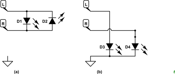
One LED's plus pin is connected to the left channel and the other LED's plus pin is connected to the right channel. The minus pins are connected to the other respective channels.

That means that they'll only light when there is a difference between the two channels. If you have a mono recording or a stereo recording with the same signal on both channels then you will have no voltage difference between L and R. I don't understand how you got this to work at all unless you have zero volume on one channel or you inverted the signal on one channel to maximise the difference in L and R.

schematic

simulate this circuit – Schematic created using CircuitLab

Figure 1. (a) What you've got. (b) What you need.

If you've got the same signal on L and R then you would have to wire as shown in Figure 1b but would need a higher output level than if you were running (a) with anti-phase signals.

The signal on the right channel is inverted to the signal on the left.

That is critical information and should be mentioned in your question.

So i do get the voltage difference necessary to send the signal.

Yes, you would.

I forgot to mention: If the mono signal solution + different circuitry is more reliable, I'll absolutely switch over.

No, your complimentary (inverted) signal gives twice the voltage to the LEDs in (a) than you would get in (b).


Standard IR transmission uses 38 kHz modulation on the IR light. Your phone's audio won't go above 20 kHz so I don't know how this is working at all.

\$\endgroup\$
5
  • 1
    \$\begingroup\$ I already assumed the wave files were okay, but i checked them using Audacity to make sure. The signal on the right channel is inverted to the signal on the left. So i do get the voltage difference necessary to send the signal. \$\endgroup\$ Commented Oct 4, 2020 at 10:33
  • \$\begingroup\$ I forgot to mention: If the mono signal solution + different circuitry is more reliable, i'll absolutely switch over. \$\endgroup\$ Commented Oct 4, 2020 at 10:35
  • \$\begingroup\$ See the update. \$\endgroup\$
    – Transistor
    Commented Oct 4, 2020 at 11:27
  • \$\begingroup\$ It doesn't work on the phone. It did only once by chance, but that's all. But there must be a possibilty since a few apps are out there who do use the phone's audio for IR stuff. I figured that maybe the sampling rate is important, because how else could we reach 38khz? \$\endgroup\$ Commented Oct 4, 2020 at 11:47
  • 1
    \$\begingroup\$ Audio hardware can't pass 38 KHz signals, they have to be applied after. And you've already lost them when removed by the IR detector module you used at the start. \$\endgroup\$ Commented Oct 4, 2020 at 11:49

Your Answer

By clicking “Post Your Answer”, you agree to our terms of service and acknowledge you have read our privacy policy.

Not the answer you're looking for? Browse other questions tagged or ask your own question.