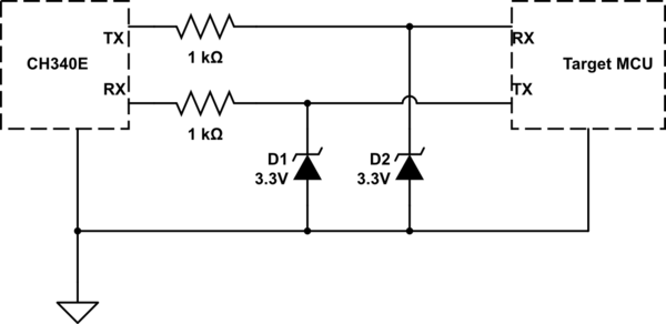
I want to make a usb-serial adapter using CH340E(datasheet) chip, and use it on 3.3V or 5V microcontrollers alike, without using a switch or jumper. I've read this and this questions but there, the target voltage is known so things are a bit easier.
the CH340 has an internal regulator so any signal above 3V is accepted as HI.
in the datasheet [which is a little unclear] is mentioned :
CH340 chip supports 5V and 3.3V power voltage. When using 5V source power, the VCC pin input 5V power and the V3 pin should connect with decoupling 0.1uF capacitor. When using 3.3V power voltage, connects V3 with VCC, both input 3.3V power voltage, and the other circuit voltage which connected with CH340 cannot exceed 3.3V.
I have to set CH340 VCC to 3V or 5V, so here are some solutions:
- Use the 5V supply. in this case, the CH340E would be fine for any range of logic levels between 3 to 5 volts. the downside is, the idle-Hi tx/rx pins of CH340E are 5V (I've measured it) now and the burden, is on the protection diodes of the microcontroller. I can use a series resistor (1K), but it's a little unpleasing to rely on protection diodes.
- Use the 3V supply. in this case, the CH340E will use it's own internal regulator as it's VCC. the problem is, that it's mentioned in the datasheet(above quotation) that in this case, we shouldn't connect anything higher than 3.3V to it. (no protection diodes ?)
- Use 3.3V zeners with a series resistor. I just came up with the idea. in this case, it is guaranteed the line level on tx/rx pair stays in the range of 3.3 volts. so the burden would be on these zeners. a series 1K resistor would ease it for the zeners.
- Using a combination of buffer gates (e.g. 74HC125). it seems a little overkill for the situation.

simulate this circuit – Schematic created using CircuitLab
- Am I right about the (1) and (2) ?
- Is the method of (3) correct? if yes, would there be unexpected behaviour (e.g. limited baudrate values)?
